Semi-automatic coil binding machine

a coil binding machine and semi-automatic technology, applied in the field of binding machines, can solve the problems of wasting more time in book binding and being relatively disadvantageous in mass production, and achieve the effect of saving manpower and tim

Inactive Publication Date: 2013-03-14
INNOSTAR TECH PTE
View PDF12 Cites 0 Cited by
  • Summary
  • Abstract
  • Description
  • Claims
  • Application Information

AI Technical Summary

Benefits of technology

[0006]The object of the present invention is to save manpower and time by rendering one semi-automatic coil binding machine used to cut any spiral coil's length and perform a bookbinding operation automatically.

Problems solved by technology

This step completed by hands, however, spends more time in bookbinding and is relatively disadvantageous to mass production because of bulk papers to be printed for books in general.

Method used


Image

  • Semi-automatic coil binding machine
  • Semi-automatic coil binding machine
  • Semi-automatic coil binding machine

Examples


Embodiment Construction

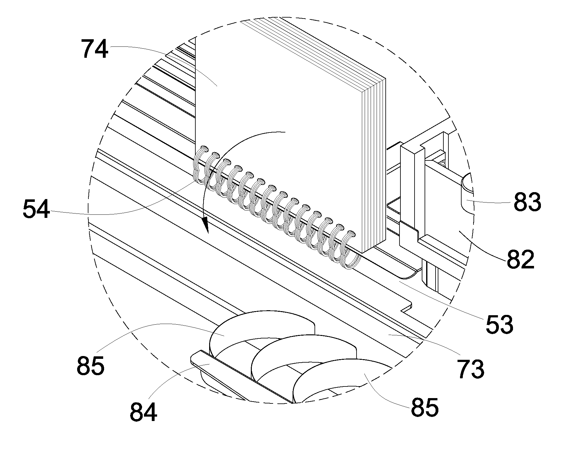
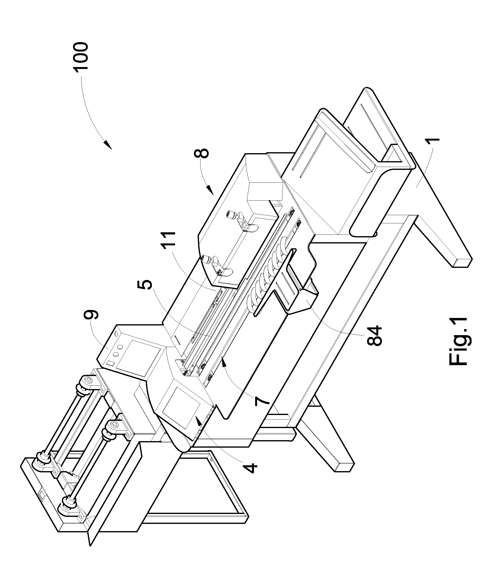
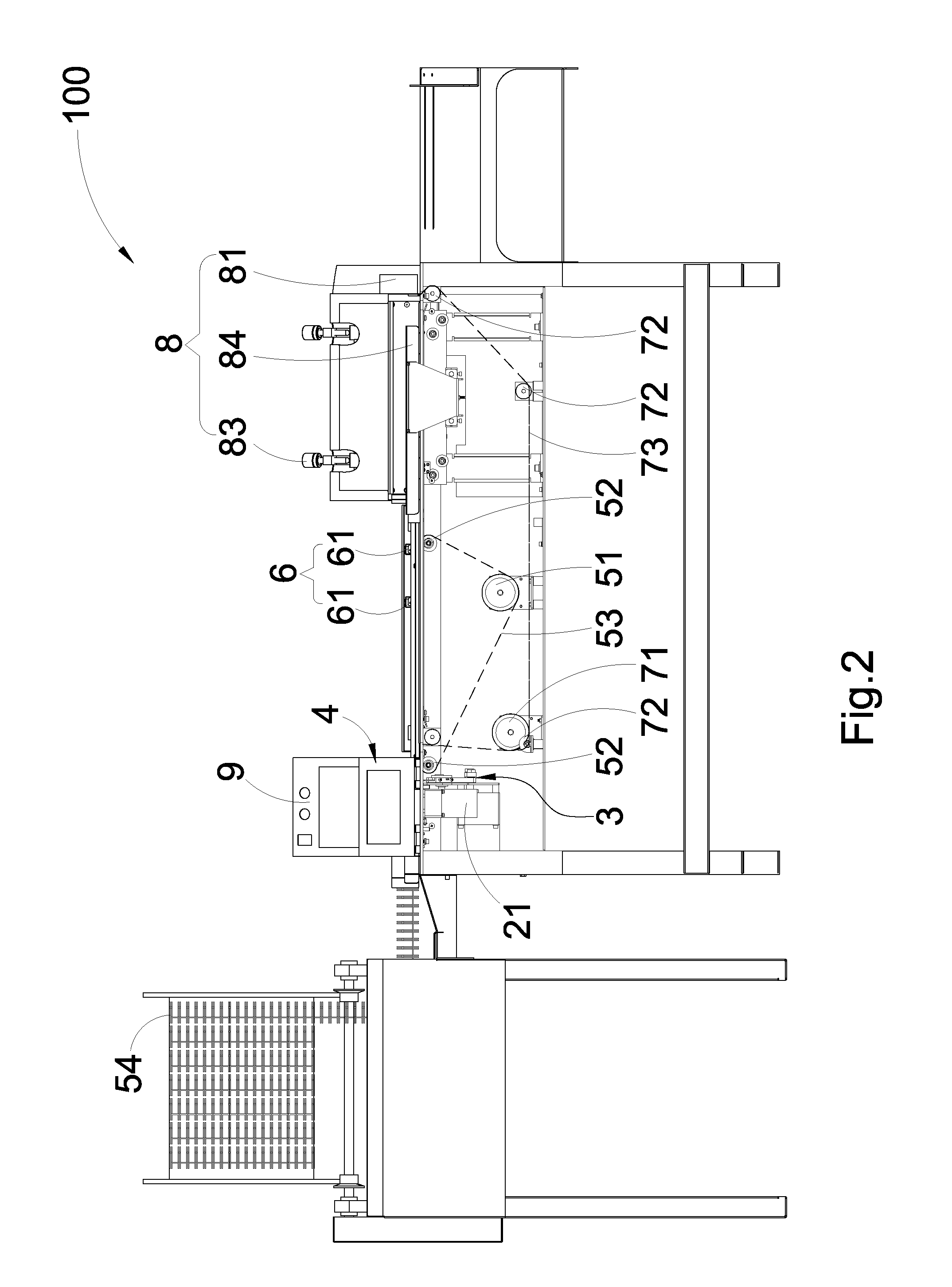
[0028]Referring to FIGS. 1 and 2 which illustrate the present invention renders a semi-automatic coil binding machine 10 which comprises a machine base 1, a coil pitch control mechanism 2, a cutting mechanism 3, a shield 4, a coil conveyor mechanism 5, a coil stop mechanism 6, a document conveyor mechanism 7, a press fit mechanism 8 and a control unit 9.

[0029]The machine base 1 is securely placed on one flat surface (e.g., ground) and equipped with a binding platform 11.

[0030]Referring to FIGS. 3, 4, 5 and 6 which illustrate the coil pitch control mechanism 2 comprises a pitch control motor 21, an assembly / disassembly device 22, a pitch control gear 23 and a regulator device 24. The pitch control motor 21 is mounted on the regulator device 24 for generation of a turning power; the assembly / disassembly device 22 is connected to the pitch control motor 21 by means of one disassembly mechanism; the pitch control gear 23 is installed on the assembly / disassembly device 22 and the binding...


PUM


Abstract

A semi-automatic coil binding machine includes a machine b as e, a coil pitch control mechanism, a cutting mechanism, a coil conveyor mechanism, a coil stop mechanism, a document conveyor mechanism and a press fit mechanism: the coil pitch control mechanism conveys a spiral coil to a predetermined length; the cutting mechanism cuts the spiral coil to a predetermined length; the coil conveyor mechanism conveys the cut spiral coil; the coil stop mechanism stops the spiral coil at a threading position from which the spiral coil is threaded onto a pile of documents; the document conveyor mechanism conveys the pile of documents with a spiral coil threaded to a press-fit position at which the spiral coil and the documents are pressed by the press fit mechanism for the spiral coil securely bonded to the documents at bookbinding and substantially increased throughput.

Description

BACKGROUND OF THE INVENTION[0001]1. Field of the Invention[0002]The present invention relates to a binding machine, especially a semi-automatic coil binding machine.[0003]2. Description of the Prior Art[0004]For the purpose of each leaf separately thumbed or torn off from a stack of documents, a row of holes should be punched along one side of a pile of papers for one spiral coil threaded.[0005]A spiral coil to be introduced into holes on a pile of papers should be cut to a predetermined length which matches one document's specific length and gradually guided into holes on papers by one operator. This step completed by hands, however, spends more time in bookbinding and is relatively disadvantageous to mass production because of bulk papers to be printed for books in general.SUMMARY OF THE INVENTION[0006]The object of the present invention is to save manpower and time by rendering one semi-automatic coil binding machine used to cut any spiral coil's length and perform a bookbinding ...

Claims


Application Information

Patent Timeline
Patent Type & Authority Applications(United States)
IPC IPC(8): B42B5/12
CPCB42B5/12B42B5/123
Inventor CHIANG, CHOU-CHIH
Owner INNOSTAR TECH PTE
Why Eureka
Try Eureka