Method and device for maintaining constant temperature
A technology for maintaining constant temperature and equipment. It is used in lighting and heating equipment, cooling fluid circulation devices, household appliances, etc. It can solve the problems of short heat preservation time and uncontrollable external ambient temperature, and achieve extended heat preservation time, improve temperature regulation efficiency, The effect of low energy consumption and temperature control
- Summary
- Abstract
- Description
- Claims
- Application Information
AI Technical Summary
Problems solved by technology
Method used
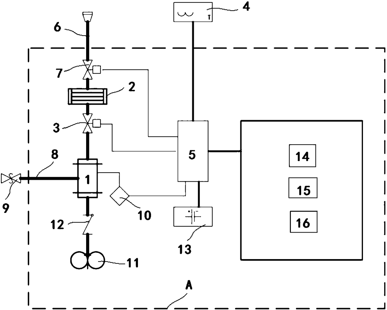
Image

Examples
specific Embodiment 1
[0037] This embodiment discloses a more preferred embodiment of the method for maintaining a constant temperature, including steps:
[0038] S10: keeping the dry ice in an insulated bucket;
[0039] S20: Detect the external ambient temperature of the thermal insulation bucket;
[0040] S30: When the external ambient temperature of the thermal insulation bucket exceeds the preset temperature range, the thermal insulation bucket is opened, and the low-temperature carbon dioxide gas obtained by the heat absorption and sublimation of the dry ice in the thermal insulation bucket is transported to a heat-collecting structure, and the low-temperature carbon dioxide gas is absorbed by the heat-collecting structure heat in the external environment;
[0041] S40: after a preset time after opening the thermal insulation bucket, detect the external ambient temperature of the thermal insulation bucket again;
[0042] S50: When the external ambient temperature of the thermal insulation bu...
specific Embodiment 2
[0048] Specific embodiment 2 discloses another embodiment of the method for maintaining a constant temperature, the steps of which are basically the same as those of specific embodiment 1, the only difference being that the low-temperature carbon dioxide gas obtained by the endothermic sublimation of dry ice in the heat preservation bucket in step S50 The discharge methods are different. In step S50 of this embodiment, the low-temperature carbon dioxide gas obtained by the heat absorption and sublimation of the dry ice in the heat preservation bucket first passes through the heat collection structure, and then is discharged into the external environment through the rapid discharge port, that is to say , in this embodiment, the quick discharge port communicates with the heat preservation bucket through the heat collecting structure, of course, the fast discharge port can also be regarded as an exhaust port of the heat collecting structure.
specific Embodiment 3
[0049] Embodiment 3 discloses another embodiment of the method for maintaining a constant temperature, the steps of which are basically the same as in Embodiment 1, the only difference being that the method for maintaining a constant temperature in this embodiment also includes steps before step S30: S80: When the external ambient temperature exceeds the preset temperature range and the exceeded temperature value is greater than the preset exceeding range, open the thermal insulation bucket, and the low-temperature carbon dioxide gas obtained by the heat absorption and sublimation of the dry ice in the thermal insulation bucket is directly discharged into the external environment of the thermal insulation bucket. That is to say, when it is detected that the external environment temperature is too high, the low-temperature carbon dioxide gas does not absorb external heat through the heat collecting structure, but is directly discharged into the external environment to absorb heat...
PUM
 Abstract
Description
Claims
Application Information