
Test method for working resistance of loader test bench and front-end working part of loader

A technology of loaders and test benches, applied in the field of machinery, can solve the problems of low insertion speed control accuracy, unfavorable test results, and low reliability, and achieve the effects of widely simulating the scope of application, shortening the research cycle, and improving test accuracy

Active Publication Date: 2019-11-05
GUANGXI UNIVERSITY OF TECHNOLOGY
View PDF5 Cites 2 Cited by
  • Summary
  • Abstract
  • Description
  • Claims
  • Application Information

AI Technical Summary

Problems solved by technology

[0003] At present, the test system of loaders at home and abroad basically adopts the whole machine test for the operation resistance test, which cannot accurately control the working parameters and environmental conditions. The experimental data is completely based on the experience of the experimenters on the whole machine.
[0004] Moreover, the existing test method is based on the whole machine, and the pin sensor is installed at the connecting joint between the bucket and the linkage mechanism. The disadvantage is that the pin sensor connecting the Z connecting rod and the bucket will affect the movement of the boom. The pin sensor at the connection with the bucket measures the Z axial torque and X, Z axial force, which reduces the measurement accuracy
[0005] Existing test systems all use customized 2D or 3D pin sensors, which are very costly and have low accuracy +-3%
[0006] There are too many interference factors in the whole machine test. For example, the whole machine test method can only measure the force of the bucket, and the three-dimensional force sensor at the lower end is affected by the pin sensor at the upper end. The test is not accurate enough, and the test results are also affected by the loading machine. The impact of wheel vibration; at the same time, the insertion speed control accuracy is low, which directly leads to inaccurate measurement results; and this method does not have the function of replacing the bucket and boom, and the test system has poor versatility; the sensor used is a special two-dimensional or three-dimensional pin Force sensor, high cost; the installation of the sensor adopts interference fit, which is difficult to assemble and maintain; the connection stiffness of the sensor is limited, easy to damage, and low reliability; human operation has a great impact on the accuracy of the repeatable test results
These are not good for the test results
[0007] For the whole machine test, each test must be suspended or replaced according to the physical exertion of the test personnel. It is impossible to continue the test for a long time, and the research cycle takes a long time

Method used


Image

  • Test method for working resistance of loader test bench and front-end working part of loader
  • Test method for working resistance of loader test bench and front-end working part of loader
  • Test method for working resistance of loader test bench and front-end working part of loader

Examples


Embodiment 1

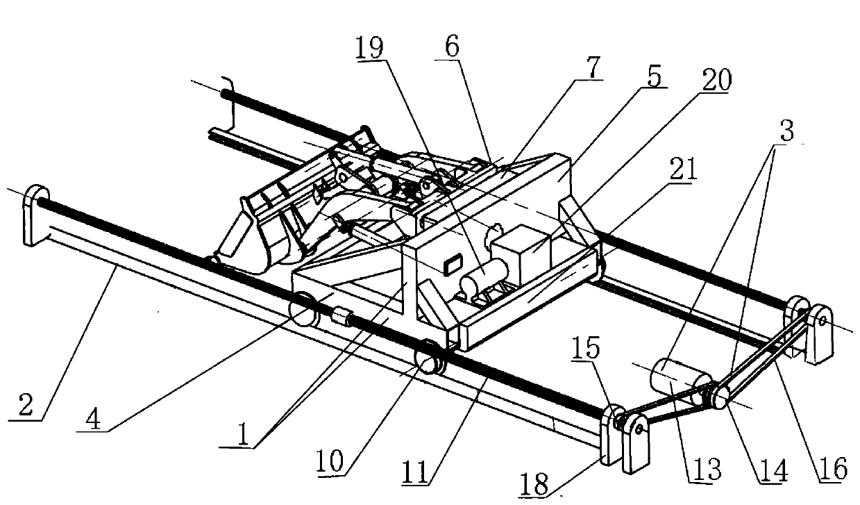
[0066] Such as Figure 1-4 Shown, the used device of the inventive method and the structure of test bench are as follows:

[0067] Including trolley 1, track 2, driving device 3;

[0068] The trolley 1 is installed on the track 2, and the driving device 3 is linked with the trolley 1 to drive the trolley 1 to move along the track;

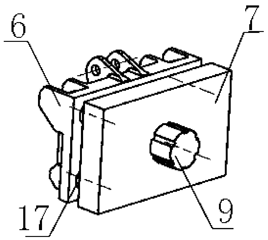
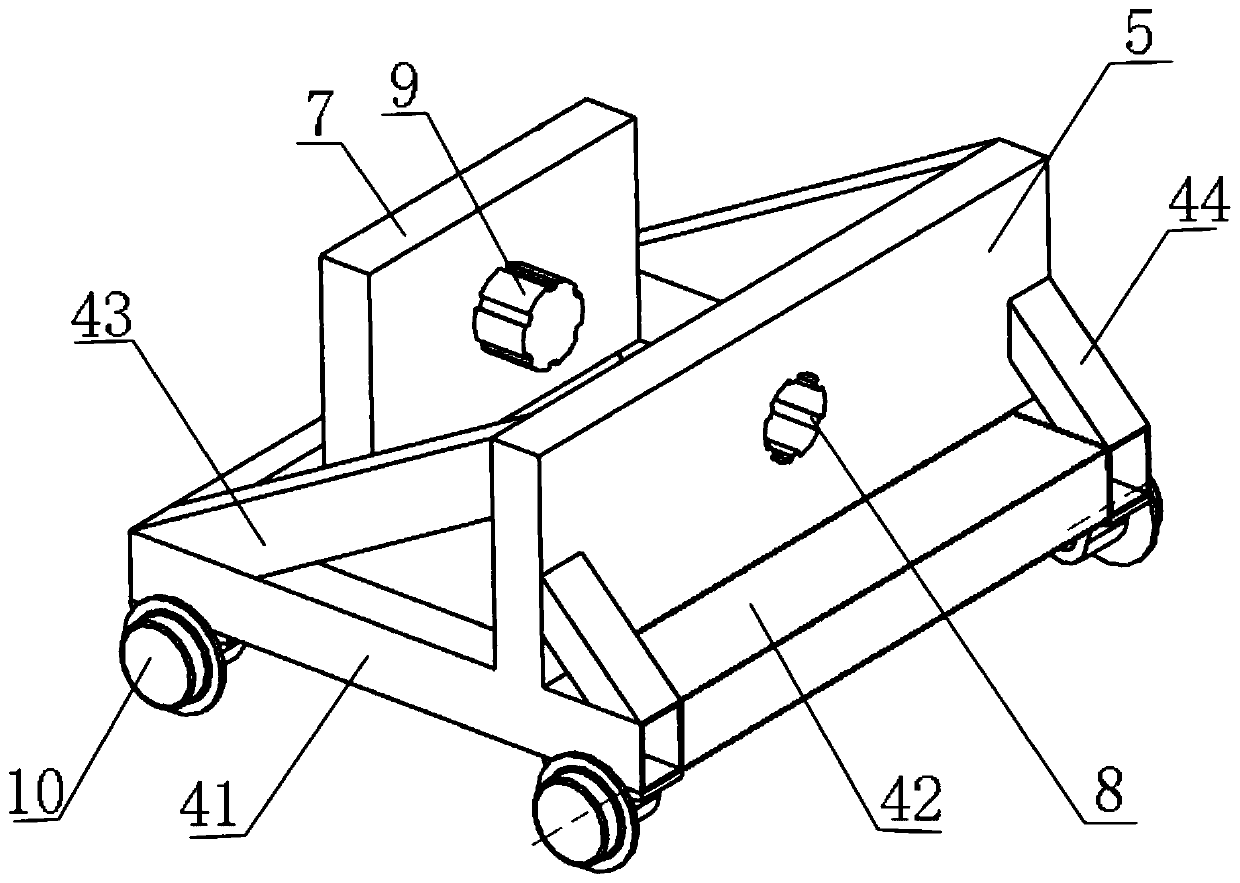
[0069] The trolley 1 includes a vehicle frame 4, a mounting plate 5, a hydraulic drive, a fixed plate 6, and a quick connecting plate 7; the vehicle frame 4 is installed on the track 2; the mounting plate 5 is vertically arranged on On the vehicle frame 4, an installation interface 8 is provided on it;

[0070] The front wall of the fixed plate 6 is provided with a mounting point for the front-end working parts of the loader; the front-end working parts of the loader are composed of a front-end working part, a boom, and a supporting hydraulic cylinder;

[0071] The rear wall of the fixed plate 6 is connected to the front wall of the fast connect...

Embodiment 2

[0082] The results of the operation resistance test of the front end of the loader are as follows:

[0083] A. Utilize the test bench with driving device, fixed plate 6 and quick connection plate 7 to set the experimental stockpile before the front end of the test bench;

[0084] B. Disassemble the loader to be tested to obtain the front-end working device; or directly assemble to obtain the front-end working device;

[0085] C. Install the front end working device on the fixed plate 6 to form the front end of the trolley;

[0086] D. Install the fixed plate 6 on the quick connecting plate 7 through the three-dimensional force sensor 17, the fixed plate 6 and the quick connecting plate (7) are parallel to each other, and then insert the quick connecting plate 7 on the mounting plate 5, so that the front end will work The device and the trolley are assembled into one;

[0087] E. Adjust the hydraulic drive device to control the front working part to reach the set height and i...


PUM


Abstract

The invention discloses a loading machine experiment table and method for testing the operation resistance of a front-end working part of a loading machine. The method employs an experiment table fortesting, wherein the experiment table comprises a trolley, a rail, and a drive device. The method comprises the following steps: installing a front-end working device on a fixed plate; installing thefixed plate on a quick connection plate through a three-dimensional force sensor; inserting the quick connection plate into an installation plate, thereby enabling the front-end working device and thetrolley to be assembled in one body; controlling a bucket to reach a set height and an insertion angle; driving the trolley to obtain the set speed to move to an experiment material pile; setting thedepth of insertion into materials; enabling the bucket to be inserted into the experiment material pile; measuring the resistance data in three directions X, Y and Z through the three-dimensional force sensor when the bucket is inserted into the experiment material pile, and calculating the working resistance of the front-end working part through the resistance data in three directions X, Y and Z. The method can enable an experiment to be carried out repeatedly in an initial state, and achieves the performance testing or measurement of the selected front-end working part.

Description

technical field [0001] The invention belongs to the technical field of machinery, and in particular relates to a loader test bench and a method for testing the working resistance of a front-end working part. Background technique [0002] Wheel loader is a kind of construction machinery with a very wide range of uses, which can complete operations such as shovel loading, unloading, handling, and leveling of bulk materials. Using different working devices, the wheel loader can complete different tasks such as bulldozing, lifting and loading and unloading wood. The traditional design methods of wheel loader working devices include analog trial and error drawing method and translation-based drawing method, but these methods are difficult to meet the design requirements, the development cycle is long, and the work is too cumbersome. Today's design is more used The design and analysis of the working device of the wheel loader is carried out by virtual prototyping technology. The...

Claims


Application Information

Patent Timeline
Patent Type & Authority Patents(China)
IPC IPC(8): G01M13/00
CPCG01M13/00
Inventor 徐武彬何锐波金隼黄中一
Owner GUANGXI UNIVERSITY OF TECHNOLOGY
Learn More