Force sensor setting method and operation resistance test method based on loader test bench
A force sensor and testing method technology, applied in the mechanical field, can solve the problems that the sensor cannot obtain accurate measurement, large vibration, and low measurement accuracy
- Summary
- Abstract
- Description
- Claims
- Application Information
AI Technical Summary
Problems solved by technology
Method used
Image
Examples
Embodiment 1
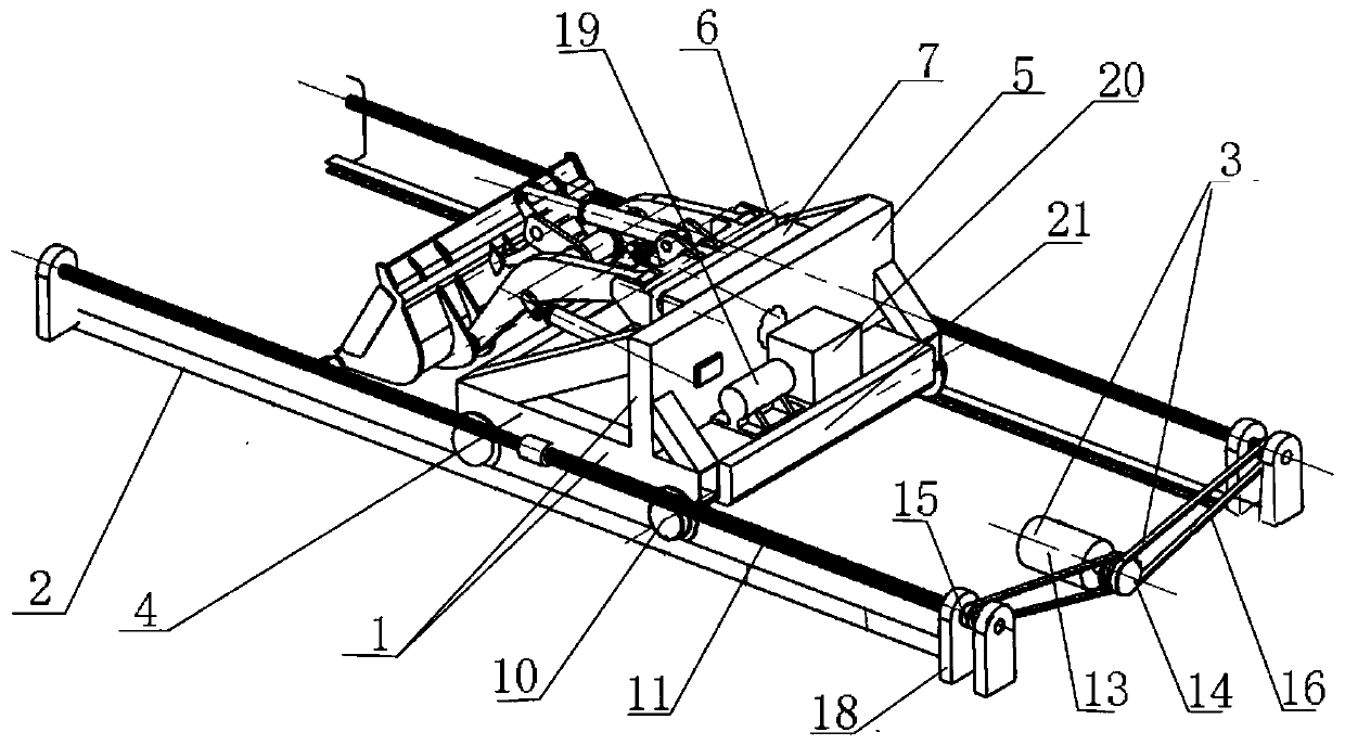
[0075] Such as Figure 1-4 Shown, the used device of the inventive method and the structure of test bench are as follows:
[0076] Including trolley 1, track 2, driving device 3;
[0077] The trolley 1 is installed on the track 2, and the driving device 3 is linked with the trolley 1 to drive the trolley 1 to move along the track;
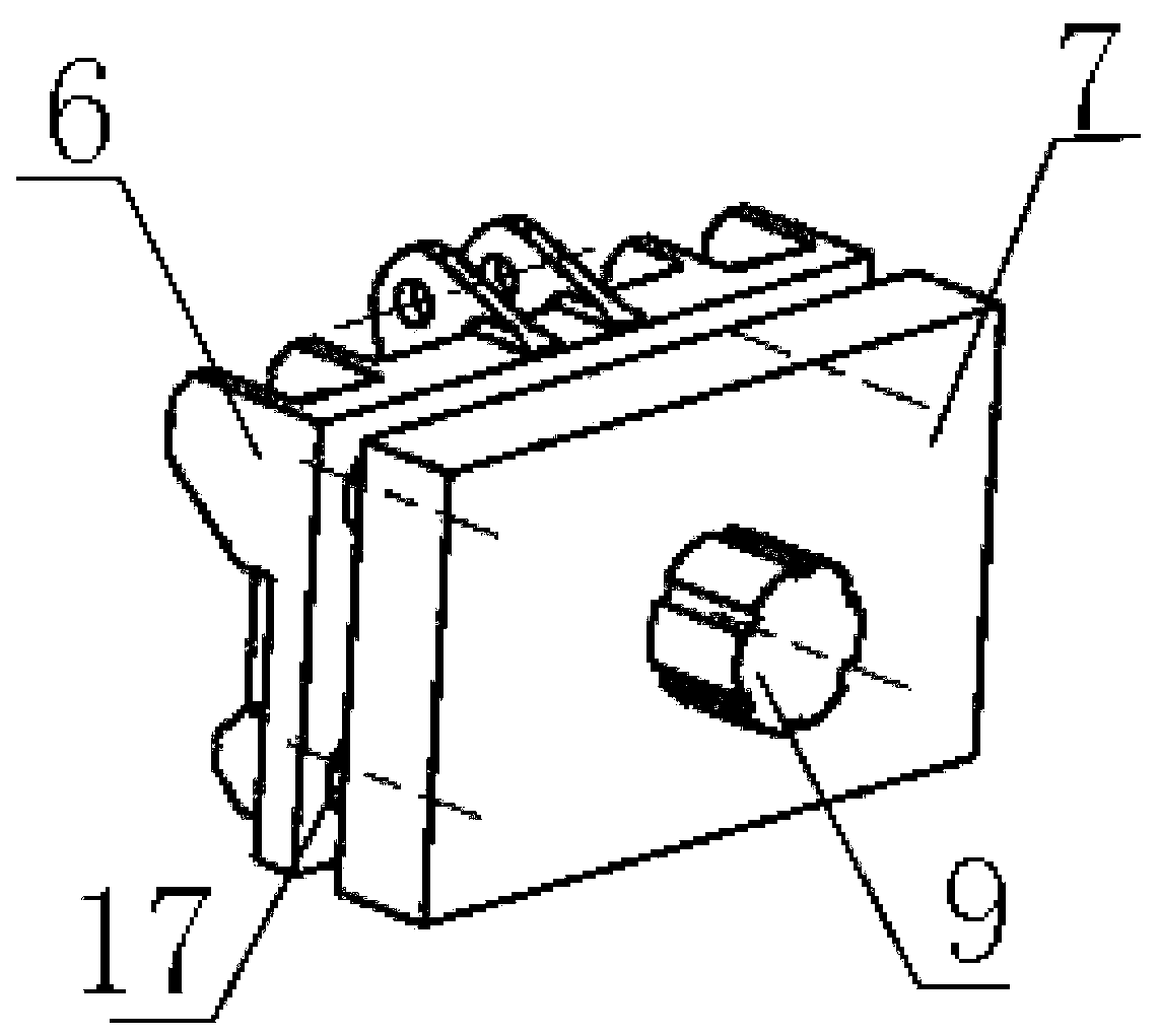
[0078] The trolley 1 includes a vehicle frame 4, a mounting plate 5, a hydraulic drive, a fixed plate 6, and a quick connecting plate 7; the vehicle frame 4 is installed on the track 2; the mounting plate 5 is vertically arranged on On the vehicle frame 4, an installation interface 8 is provided on it;
[0079] The front wall of the fixed plate 6 is provided with a mounting point for the front-end working parts of the loader; the front-end working parts of the loader are composed of a front-end working part, a boom, and a matching hydraulic cylinder;
[0080] The rear wall of the fixed plate 6 is connected with the front wall of the quick connec...
Embodiment 2
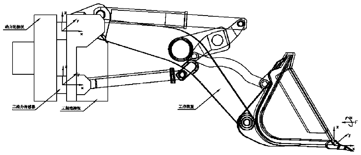
[0092] The loader model used in this experiment is a 5-ton 3-square wheel loader produced by a certain company; the force sensor setting method for the test of the front-end working part of the loader includes the following steps:
[0093] A, set the fixed plate 6 and the quick connection plate 7 parallel to each other, the rear wall of the fixed plate 6 and the front wall of the quick connection plate 7 are connected by 4 three-dimensional force sensors 17;
[0094] The front wall of the fixed plate 6 is equipped with front-end working parts of the loader, and the front-end working parts of the loader are composed of a bucket, a boom, and a supporting hydraulic cylinder;
[0095] The rear wall of the quick connecting plate 7 is connected with the trolley 1, and the trolley 1 can move in a straight line and can provide the power required by the working parts of the front end of the loader;
[0096] B. On the rear wall of the fixed plate 6, four three-dimensional force sensors ...
Embodiment 3
[0118] The loader model used in this experiment is a 5-ton 3-square wheel loader produced by a certain company; the method for testing the working resistance of the front-end working part of the loader includes the following steps:
[0119] A. First use the method of Embodiment 2 to determine the position of the three-dimensional force sensor on the fixed plate 6, and then assemble the front-end working parts of the loader, the fixed plate 6, the three-dimensional force sensor, the quick connection plate 7, and the trolley 1 to form a test device ;
[0120] B. Adjust the hydraulic drive device to control the bucket to reach the set height and insertion angle; the set height is 0.1m from the ground at the front end working part, and the set insertion angle is 23 between the bottom surface of the front end working part and the horizontal plane °;
[0121] C, start the driving device 3 to rotate forward, the set distance between the console car 1 and the experimental stockpile i...
PUM
 Abstract
Description
Claims
Application Information
 - R&D
- Intellectual Property
- Life Sciences
- Materials
- Tech Scout
- Unparalleled Data Quality
- Higher Quality Content
- 60% Fewer Hallucinations
Browse by: Latest US Patents, China's latest patents, Technical Efficacy Thesaurus, Application Domain, Technology Topic, Popular Technical Reports.
© 2025 PatSnap. All rights reserved.Legal|Privacy policy|Modern Slavery Act Transparency Statement|Sitemap|About US| Contact US: help@patsnap.com


