Loader testing experiment table based force sensor arranging method and operation resistance testing method

A force sensor and loader technology, applied in the field of machinery, can solve the problems of not having to replace the bucket and boom, poor repeatability, and only measuring the force of the bucket part.

Active Publication Date: 2018-08-03
GUANGXI UNIVERSITY OF TECHNOLOGY
View PDF11 Cites 9 Cited by
  • Summary
  • Abstract
  • Description
  • Claims
  • Application Information

AI Technical Summary

Problems solved by technology

The whole machine test method has the following shortcomings: (1) only the force of the bucket can be measured; (2) the measurement accuracy is not high
There are three reasons: (a) The pin sensors at the upper/lower hinge of the bucket affect each other, so that the sensors cannot be accurately measured
(b) During the experiment, the connection between the wheel of the loader and the ground is poor, resulting in large vibrations, which interfere with the measurement results
(c) In the whole machine experiment, the control accuracy of shovel loading and insertion speed is low, and the repeatability is poor, which is not conducive to accurately obtain the relationship between operation

Method used


Image

  • Loader testing experiment table based force sensor arranging method and operation resistance testing method
  • Loader testing experiment table based force sensor arranging method and operation resistance testing method
  • Loader testing experiment table based force sensor arranging method and operation resistance testing method

Examples


Embodiment 1

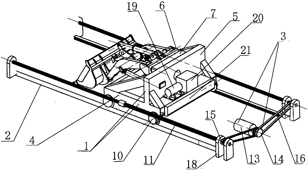
[0075] like Figure 1-4 Shown, the used device of the inventive method and the structure of test bench are as follows:

[0076] Including trolley 1, track 2, driving device 3;

[0077] The trolley 1 is installed on the track 2, and the driving device 3 is linked with the trolley 1 to drive the trolley 1 to move along the track;

[0078] The trolley 1 includes a vehicle frame 4, a mounting plate 5, a hydraulic drive, a fixed plate 6, and a quick connecting plate 7; the vehicle frame 4 is installed on the track 2; the mounting plate 5 is vertically arranged on On the vehicle frame 4, an installation interface 8 is provided on it;

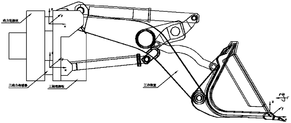
[0079] The front wall of the fixed plate 6 is provided with a mounting point for the front-end working parts of the loader; the front-end working parts of the loader are composed of a front-end working part, a boom, and a supporting hydraulic cylinder;

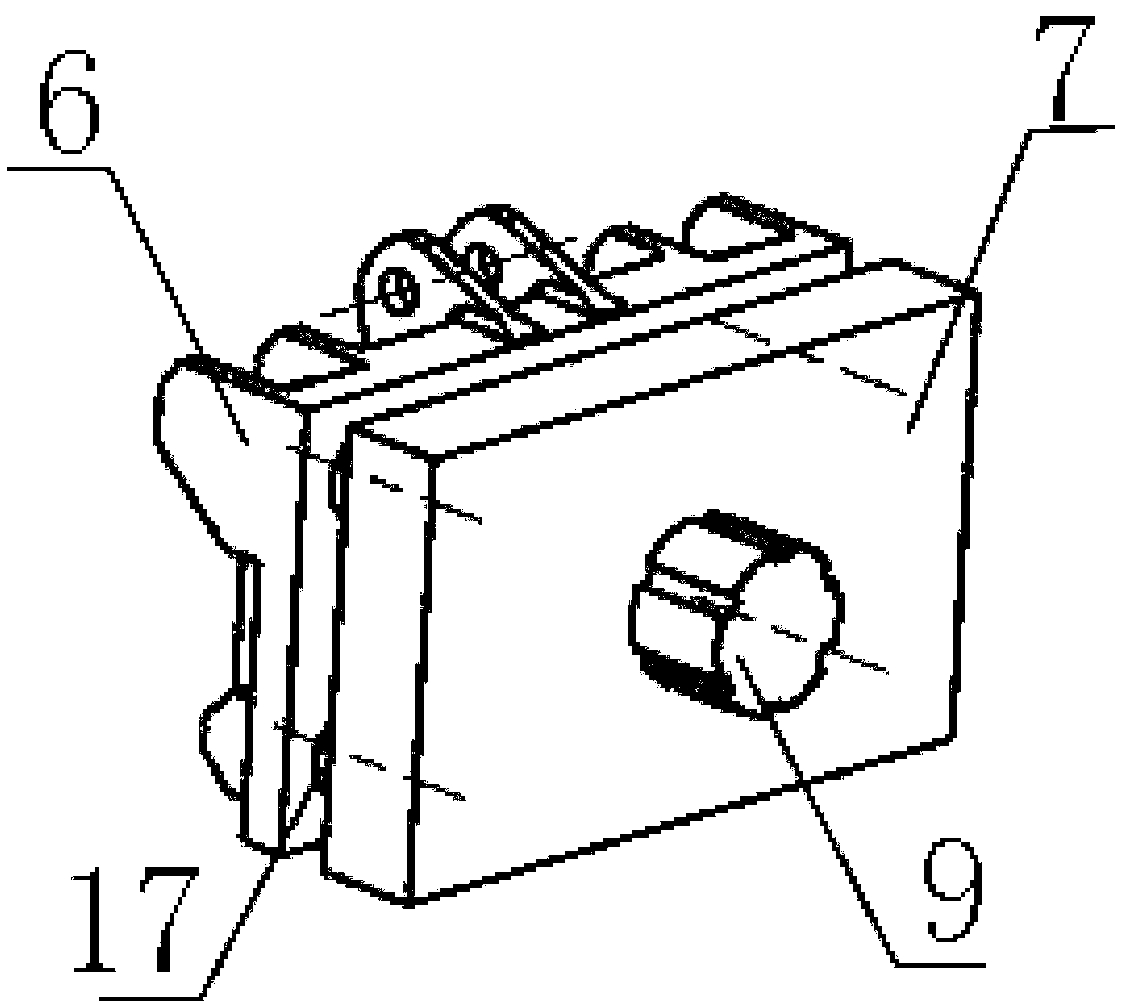
[0080] The rear wall of the fixed plate 6 is connected with the front wall of the quick connect...

Embodiment 2

[0092] The loader model used in this experiment is a 5-ton 3-square wheel loader produced by a certain company; the force sensor setting method for the test of the front-end working part of the loader includes the following steps:

[0093] A, set the fixed plate 6 and the quick connection plate 7 parallel to each other, the rear wall of the fixed plate 6 and the front wall of the quick connection plate 7 are connected by 4 three-dimensional force sensors 17;

[0094] The front wall of the fixed plate 6 is installed with front-end working parts of the loader, and the front-end working parts of the loader are composed of a bucket, a boom, and a supporting hydraulic cylinder;

[0095] The rear wall of the quick connecting plate 7 is connected with the trolley 1, and the trolley 1 can move in a straight line and can provide the power required by the working parts of the front end of the loader;

[0096] B. On the rear wall of the fixed plate 6, four three-dimensional force sensors...

Embodiment 3

[0118] The loader model used in this experiment is a 5-ton 3-square wheel loader produced by a certain company; the method for testing the working resistance of the front-end working part of the loader includes the following steps:

[0119] A. First use the method of Embodiment 2 to determine the position of the three-dimensional force sensor on the fixed plate 6, and then assemble the front-end working parts of the loader, the fixed plate 6, the three-dimensional force sensor, the quick connection plate 7, and the trolley 1 to form a test device ;

[0120] B. Adjust the hydraulic drive device to control the bucket to reach the set height and insertion angle; the set height is 0.1m from the ground at the front end working part, and the set insertion angle is 23 between the bottom surface of the front end working part and the horizontal plane °;

[0121] C, start the driving device 3 to rotate forward, the set distance between the console car 1 and the experimental stockpile i...


PUM


Abstract

The invention discloses a loader testing experiment table based force sensor arranging method. The method includes steps of A, arranging a fixed board and a quick connection board parallel to each other, wherein the rear wall of the fixed board is connected with the front wall of the quick connection board through n three-dimensional force sensors; B, arranging n three-dimensional force sensors onthe rear wall of the fixed board in advance and calibrating pre-arrangement positions of the three-dimensional force sensors; C, applying pressure on a front working component of a loader, wherein each three-dimensional force sensor can display force magnitude and direction of a test point directly and the magnitude and the direction of the applied force can be obtained through calculation. The invention also discloses a testing method for operation resistance of working components of the loader after arrangement of the loader testing experimental table and the force sensors. According to theinvention, performance test study or measurement can be performed on the selected front end working component.

Description

technical field [0001] The invention belongs to the technical field of machinery, and in particular relates to a method for testing the working resistance of front-end working parts of a loader. Background technique [0002] Wheel loader is a kind of construction machinery with a very wide range of uses, which can complete operations such as shovel loading, unloading, handling, and leveling of bulk materials. Using different working devices, the wheel loader can complete different tasks such as bulldozing, lifting and loading and unloading wood. The traditional design methods of wheel loader working devices include analog trial and error drawing method and translation-based drawing method, but these methods are difficult to meet the design requirements, the development cycle is long, and the work is too cumbersome. Today's design is more used The design and analysis of the working device of the wheel loader is carried out by virtual prototyping technology. These designed a...

Claims


Application Information

Patent Timeline
IPC IPC(8): G01L5/00G01M99/00
CPCG01L5/0061G01M99/005
Inventor 徐武彬何锐波李冰范丹丹黄中一
Owner GUANGXI UNIVERSITY OF TECHNOLOGY
Why Eureka
Try Eureka