
Quasi-resonance flyback switching power supply system

A switching power supply and quasi-resonance technology, which is applied in the direction of control/regulation system, electrical components, and adjustment of electrical variables, can solve the problems of system noise index deterioration, feedback signal fluctuation, falling outside the predetermined frequency range, etc., to solve EMI problem, avoiding the effect of system output ripple and noise becoming larger

Active Publication Date: 2018-07-31
ON BRIGHT ELECTRONICS SHANGHAI
View PDF4 Cites 15 Cited by
  • Summary
  • Abstract
  • Description
  • Claims
  • Application Information

AI Technical Summary

Problems solved by technology

[0015] In many application scenarios, the operating frequency of the quasi-resonant flyback switching power supply system will be limited within a certain range
For a quasi-resonant flyback switching power supply system with frequency shaking, when the system operating frequency is close to the set upper limit frequency or lower limit frequency, the system operating frequency after superimposed frequency shaking may fall outside the predetermined frequency range, which may Causes the moment in which the power switch switches from the off state to the on state to bounce repeatedly between several adjacent resonant valleys in its drain voltage
This repeated beating will cause the system output voltage or current and the system output voltage or current feedback signal to fluctuate, resulting in larger system output ripple
In addition, when the operating frequency of the system fluctuates greatly, the frequency components falling in the audio region will also increase, which will greatly deteriorate the system noise index

Method used


Image

  • Quasi-resonance flyback switching power supply system
  • Quasi-resonance flyback switching power supply system
  • Quasi-resonance flyback switching power supply system

Examples


Embodiment Construction

[0039] Features and exemplary embodiments of various aspects of the invention will be described in detail below. In the following detailed description, numerous specific details are set forth in order to provide a thorough understanding of the present invention. It will be apparent, however, to one skilled in the art that the present invention may be practiced without some of these specific details. The following description of the embodiments is only to provide a better understanding of the present invention by showing examples of the present invention. The present invention is by no means limited to any specific configurations and algorithms presented below, but covers any modification, substitution and improvement of elements, components and algorithms without departing from the spirit of the invention. In the drawings and the following description, well-known structures and techniques have not been shown in order to avoid unnecessarily obscuring the present invention.

...


PUM


Abstract

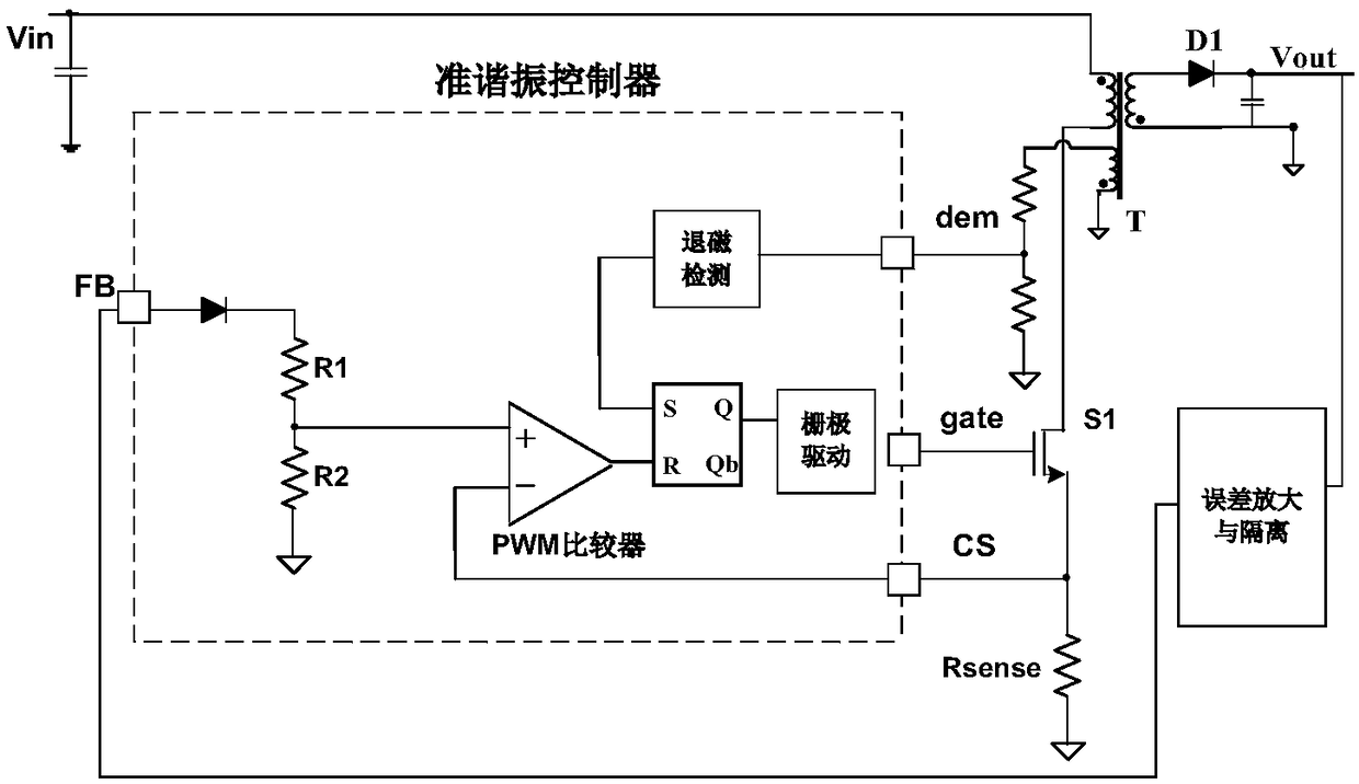
The present invention discloses a quasi-resonance flyback switching power supply system. The system comprises a transformer, a power switch, and a quasi-resonance controller consisting of a jitter frequency module and a valley bottom control module. The jitter frequency module regulates the switching frequency of the power switch through regulation of a peak current flowing through a primary winding of the transformer, or regulates the switching frequency of the power switch through addition of an advance value or a delay value at the resonance valley bottom of a drain electrode voltage of thepower switch; and the valley bottom control module performs operation and processing of a size relation of the switching frequency of the power switch and a first reference frequency and a second reference frequency to obtain increased valley bottom signals or decreased valley bottom signals so as to control the power switch to convert from an off state to an on state at the predetermined resonance valley bottom of the drain electrode voltage thereof according to the increased valley bottom signals or the decreased valley bottom signals.

Description

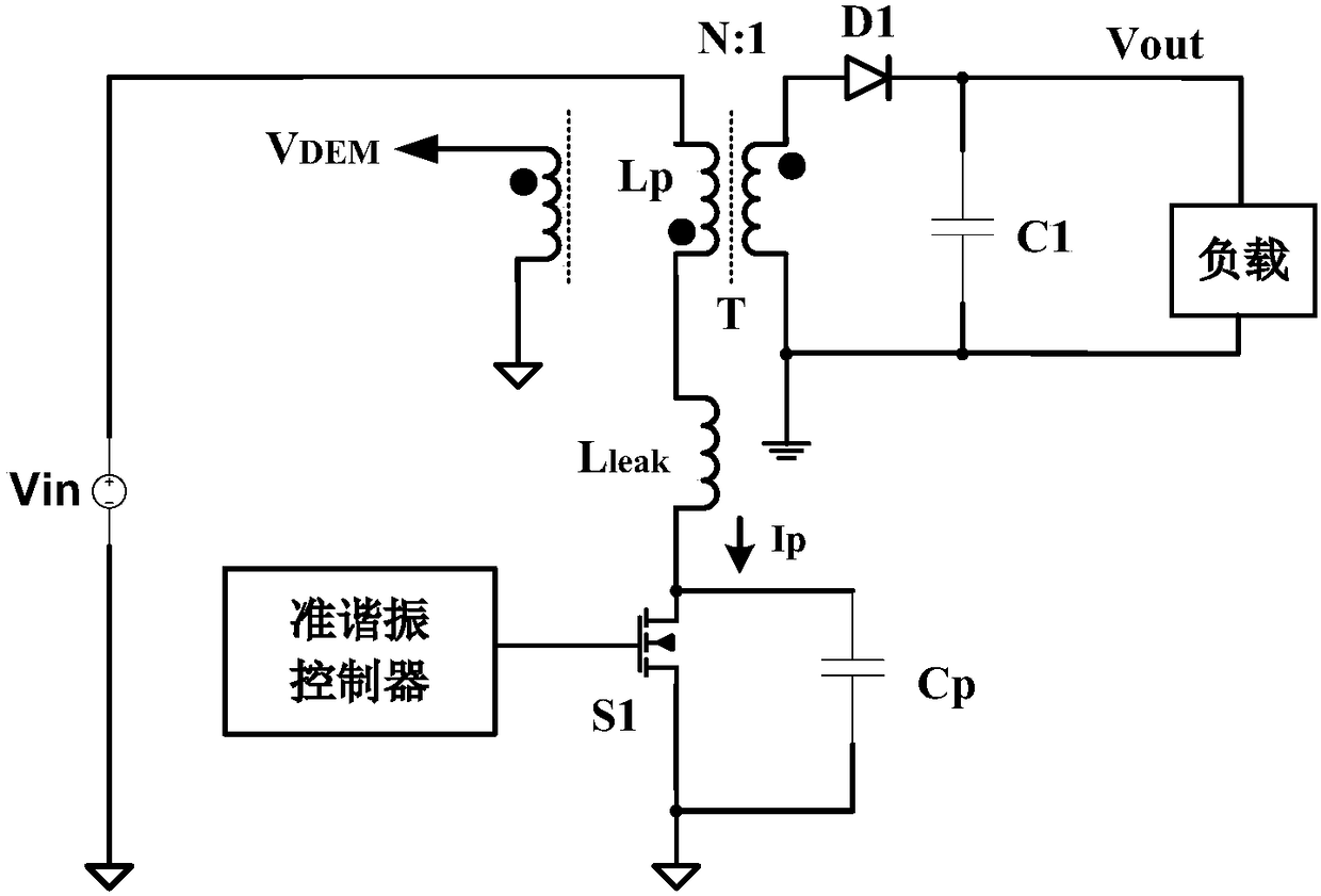
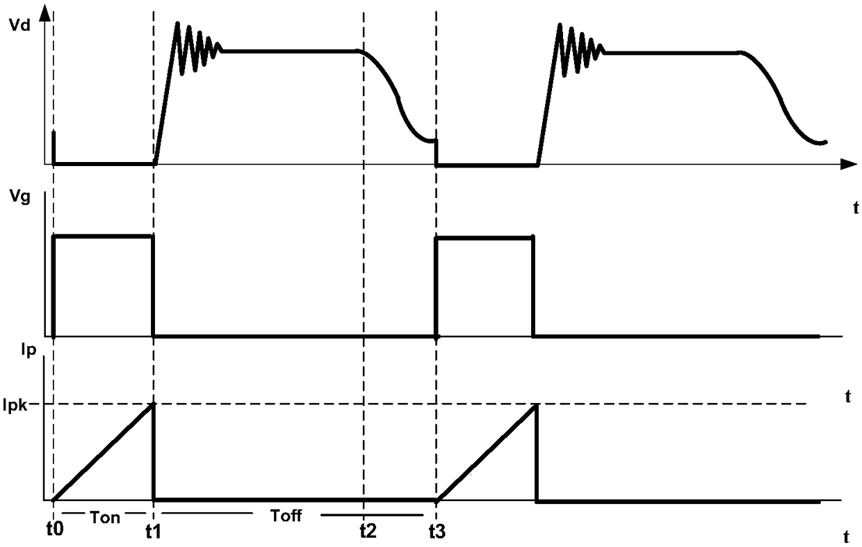
technical field [0001] The invention relates to the field of circuits, in particular to a quasi-resonant flyback switching power supply system. Background technique [0002] figure 1 A schematic diagram of a conventional quasi-resonant flyback switching power supply system is shown. figure 2 show figure 1 The waveform diagram of the drain voltage Vd, the gate voltage Vg of the power switch S1 in the system shown, and the current Ip flowing through the primary winding of the transformer T, where Ton is the conduction time of the power switch S1, and Toff is the power The off time of switch S1. Such as figure 2 As shown, when the power switch S1 is in the off state, after the main inductance Lp of the transformer T is demagnetized, the main inductance Lp of the transformer T and the parasitic capacitance Cp of the power switch S1 are free to resonate. at this time, figure 1 The quasi-resonant controller in the system shown can control the power switch S1 to switch from...

Claims


Application Information

Patent Timeline
Patent Type & Authority Applications(China)
IPC IPC(8): H02M3/335
CPCH02M3/33523Y02B70/10
Inventor 褚海林元
Owner ON BRIGHT ELECTRONICS SHANGHAI
Learn More