Walking motion display system and program

A technology for displaying systems and actions, applied in the directions of sensors, diagnosis, applications, etc., can solve the problems of complex device structure, poor convenience, and heavy burden on the observer, and achieve the effect of simple structure and high convenience

Active Publication Date: 2018-07-31
PANASONIC INTELLECTUAL PROPERTY MANAGEMENT CO LTD
View PDF12 Cites 2 Cited by
  • Summary
  • Abstract
  • Description
  • Claims
  • Application Information

AI Technical Summary

Problems solved by technology

[0007] However, the conventional method of clipping an image by an observer has a problem that the burden on the observer is very large.
In addition, which image to cut depends on the experience and skills of the observer. Without a good observer, the subject cannot be guided, and the convenience is poor.
In addition, in the three-dimensional motion analysis device described in Patent Document 1, the subject wears a plurality of markers and takes pictures with a plurality of cameras, so the configuration of the device is complicated.

Method used


Image

  • Walking motion display system and program
  • Walking motion display system and program
  • Walking motion display system and program

Examples


Embodiment approach

[0023] [Walk action display system]

[0024] First, use figure 1 as well as figure 2 The outline of the walking behavior display system according to this embodiment will be described.

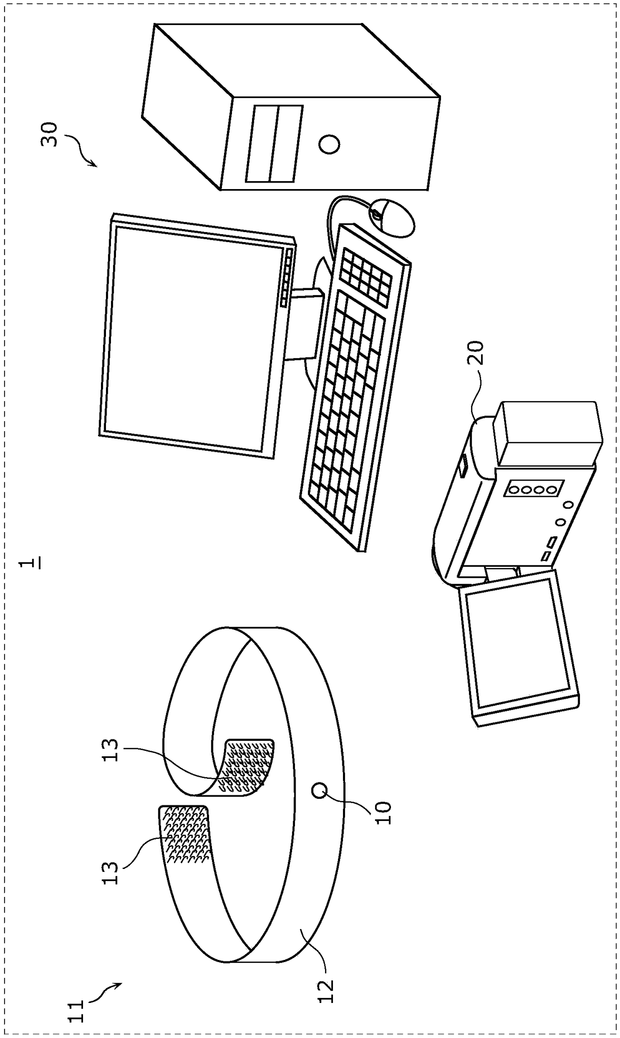
[0025] figure 1 It is a figure which shows the concrete structure of the walking behavior display system 1 concerning this embodiment.

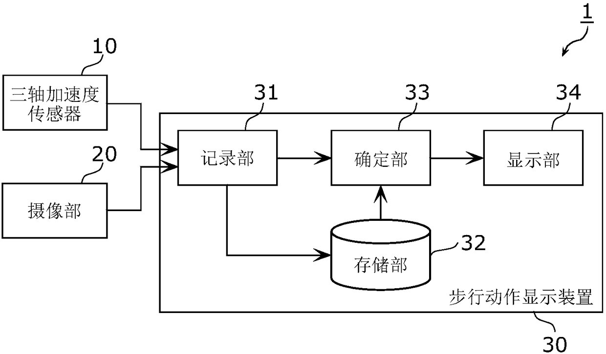
[0026] figure 2 It is a block diagram showing the functional configuration of the walking motion display system 1 according to the present embodiment.

[0027] Such as figure 1 As shown, the walking behavior display system 1 includes: a triaxial acceleration sensor 10 , an imaging unit 20 , and a walking behavior display device 30 . Such as figure 2 As shown, the walking behavior display device 30 includes a recording unit 31 , a storage unit 32 , a determination unit 33 , and a display unit 34 .

[0028] Hereinafter, each component of the walking motion display system will be described in detail using the drawings.

[0029] [Three-axis acceleratio...

Embodiment

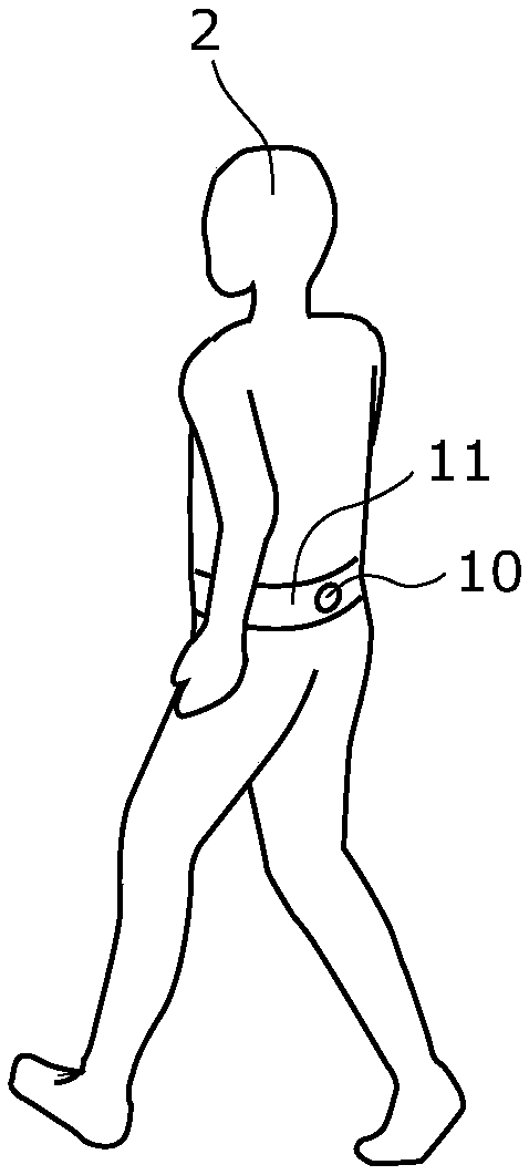
[0120] Here, use Figure 7 as well as Figure 8 An example in which an actual human being is used as the subject 2 and is measured and photographed wearing the triaxial acceleration sensor 10 will be described. In addition, in the examples, a person whose walking behavior is not appropriate is used as the test subject 2 . Therefore, on the report screen displayed on the display unit 34 , there is a difference between the operation represented by the schematic diagram and the operation represented by the representative image.

[0121] Figure 7 It is a diagram showing displacement data in the horizontal direction and vertical direction converted from acceleration data actually measured by the triaxial acceleration sensor 10 in the walking behavior display system 1 according to the present embodiment. In addition, in Figure 7 In , the horizontal axis represents the walking time, and the vertical axis represents the displacement in the horizontal or vertical direction.

[0...


PUM


Abstract

The walking motion display system (1) is provided with: a 3-axis acceleration sensor (10) that is attached to a subject (2) and measures acceleration data of the subject (2) while the subject (2) is walking; an imaging unit (20) that obtains video data showing the walking motion of the subject (2) by imaging the walking subject (2); a recording unit (31) that synchronizes and records the acceleration data and the video data; an identifying unit (33) that converts the acceleration data recorded by the recording unit (31) into horizontal displacement data and vertical displacement data and identifies an image corresponding to a representative motion during a walking cycle from the video data on the basis of the horizontal displacement data or the vertical displacement data; and a display unit (34) that also displays the image identified by the identifying unit (33) in the graphical view of the representative motion during the walking cycle.

Description

technical field [0001] The present invention relates to a gait behavior display system and a program for displaying an image showing a subject's gait behavior. Background technique [0002] Conventionally, in nursing care or rehabilitation training, the subject's gait motion was presented to the subject to guide correct gait motion. For example, a method is generally employed in which an observer cuts out a predetermined image and displays it while watching a video of the subject's walking behavior. [0003] In addition, Patent Document 1 discloses a three-dimensional motion analysis device that calculates the coordinate position of each marker from moving image data obtained by photographing a subject wearing a plurality of markers with a plurality of cameras, and calculates the coordinate position of each marker based on the calculated Coordinate position, analyze walking action. In the three-dimensional motion analysis device described in Patent Document 1, a posture ma...

Claims


Application Information

Patent Timeline
Patent Type & Authority Applications(China)
IPC IPC(8): A61B5/11
CPCG01C22/006A61B5/112A61B5/1128A61B5/743A61B2562/0219A61B2576/00G16H30/40A61B5/0077
Inventor 松村吉浩中原智治藤田智彦
Owner PANASONIC INTELLECTUAL PROPERTY MANAGEMENT CO LTD
Why Eureka
Try Eureka