
Cutting insert, cutting tool, and manufacturing method for machined product

A cutting insert, cutting edge technology, applied in cutting inserts, manufacturing tools, accessories of toolholders, etc., can solve problems such as chip clogging

Active Publication Date: 2018-07-31
KYOCERA CORP
View PDF7 Cites 2 Cited by
  • Summary
  • Abstract
  • Description
  • Claims
  • Application Information

AI Technical Summary

Problems solved by technology

For example, there are cases where the chips generated by the insert for the outer edge are not broken at an appropriate length and are excessively elongated, resulting in chip clogging

Method used


Image

  • Cutting insert, cutting tool, and manufacturing method for machined product
  • Cutting insert, cutting tool, and manufacturing method for machined product
  • Cutting insert, cutting tool, and manufacturing method for machined product

Examples


Embodiment Construction

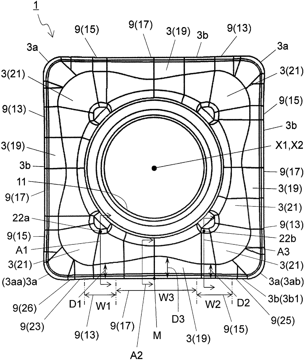
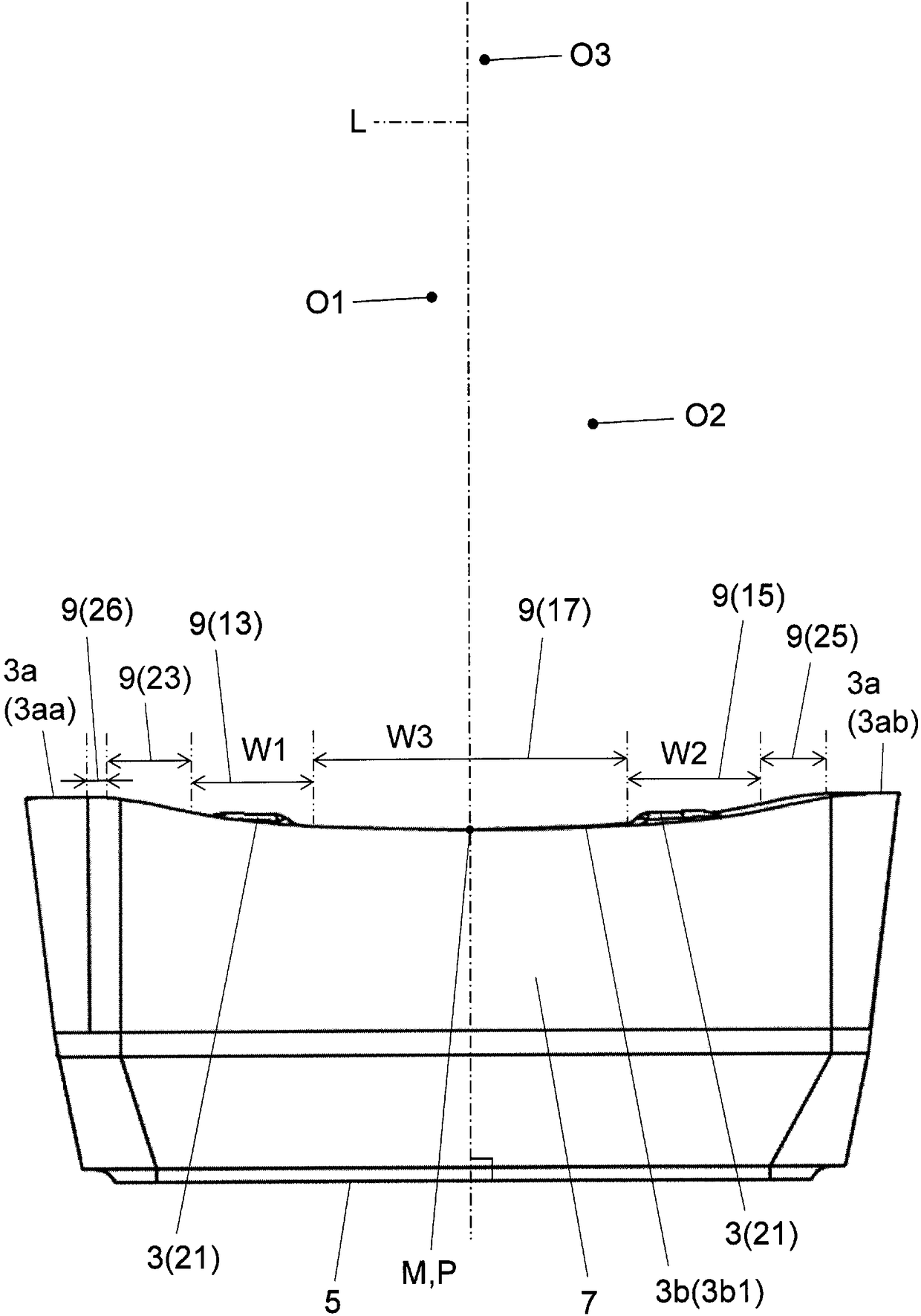
[0025] Hereinafter, a cutting insert (hereinafter also referred to as an insert) according to an embodiment of the present invention and a cutting tool including the cutting insert will be described in detail with reference to the drawings. Specifically, an insertable drill will be described as a cutting tool. Examples of the cutting tool include end mills and the like in addition to drills of the replaceable cutting edge type. In addition, as an insert, an insert for an outer cutting edge in this drill will be described.

[0026] In addition, each drawing referred to below shows only the main member necessary for description of an embodiment briefly for convenience of description. Therefore, the insert and the cutting tool of the present invention may include arbitrary constituent members not shown in the referenced drawings. In addition, the dimensions of the members in the drawings do not represent the dimensions of the actual constituent members, the dimensional ratios o...


PUM


Abstract

A cutting insert is provided with a top surface having a first corner and a second corner that are mutually adjacent, a bottom surface, side surfaces, and a cutting blade that is positioned between the first corner and the second corner in the area where the top surface and a side surface intersect. The cutting blade is provided with a first cutting blade that is positioned on the first corner side, a second cutting blade that is positioned on the second corner side, and a third cutting blade that is positioned between the first cutting blade and the second cutting blade. In a side view, the cutting blade has a curved shape that depresses increasingly toward the bottom surface side from both the first corner and the second corner the closer to the center of the cutting blade. Both the radius of curvature R1 of the first cutting blade and the radius of curvature R2 of the second cutting blade in the side view are smaller than the radius of curvature R3 of the third cutting blade in theside view. Also provided are a cutting tool equipped with the cutting insert and a method for manufacturing a machined product using the cutting tool.

Description

technical field [0001] The present invention relates to a cutting insert, a cutting tool, and a method for manufacturing a cutting workpiece. Background technique [0002] Conventionally, drills used for drilling are known as cutting tools (for example, refer to Patent Document 1). The tool described in Patent Document 1 includes a base (tool holder) having an axis, and two inserts (inserts for inner blades and inserts for outer blades) attached to the base. [0003] The insert for the inner edge and the insert for the outer edge have different distances from the axis of the tool. Therefore, the shape of the chip generated by the insert for the inner edge is different from the shape of the chip generated by the insert for the outer edge. Specifically, the shape of the chips generated by the insert for the inner edge extends helically with a pitch shorter than that of the chips generated by the insert for the outer edge, and is easy to organize. On the other hand, since th...

Claims


Application Information

Patent Timeline
Patent Type & Authority Applications(China)
IPC IPC(8): B23B51/00B23B27/14B23B27/22
CPCB23B27/141B23B2200/0471B23B2200/202B23B2200/204B23B51/00B23B27/045B23B27/143B23B27/1607B23B27/22B23B2200/0476B23B2200/123B23B2200/208B23B2200/245B23B2200/321
Inventor 石宽久
Owner KYOCERA CORP
Features
  • Generate Ideas
  • Intellectual Property
  • Life Sciences
  • Materials
  • Tech Scout
  • Unparalleled Data Quality
  • Higher Quality Content
  • 60% Fewer Hallucinations
Learn More