Naphthalene evaporation device used in preparation process of phthalic anhydride

A preparation process and evaporation device technology, applied in the direction of evaporation, evaporator accessories, chemical instruments and methods, etc., can solve the problems of naphthalene pipeline blockage, unstable output, poor evaporation effect, etc., and achieve stable production operation and high production efficiency , Heating effect evenly

Pending Publication Date: 2018-08-03
河南庆安化工高科技股份有限公司
View PDF0 Cites 1 Cited by
  • Summary
  • Abstract
  • Description
  • Claims
  • Application Information

AI Technical Summary

Problems solved by technology

[0003] The naphthalene evaporation system in the prior art is a single naphthalene evaporator. In normal production, the heavy components in industrial naphthalene accumulate at the bottom of the evaporator for a long time, and the evaporation effect is poor, the naphthalene pipeline is blocked, and the output is unstable, which affects production. factor

Method used


Image

  • Naphthalene evaporation device used in preparation process of phthalic anhydride
  • Naphthalene evaporation device used in preparation process of phthalic anhydride
  • Naphthalene evaporation device used in preparation process of phthalic anhydride

Examples


Embodiment 1

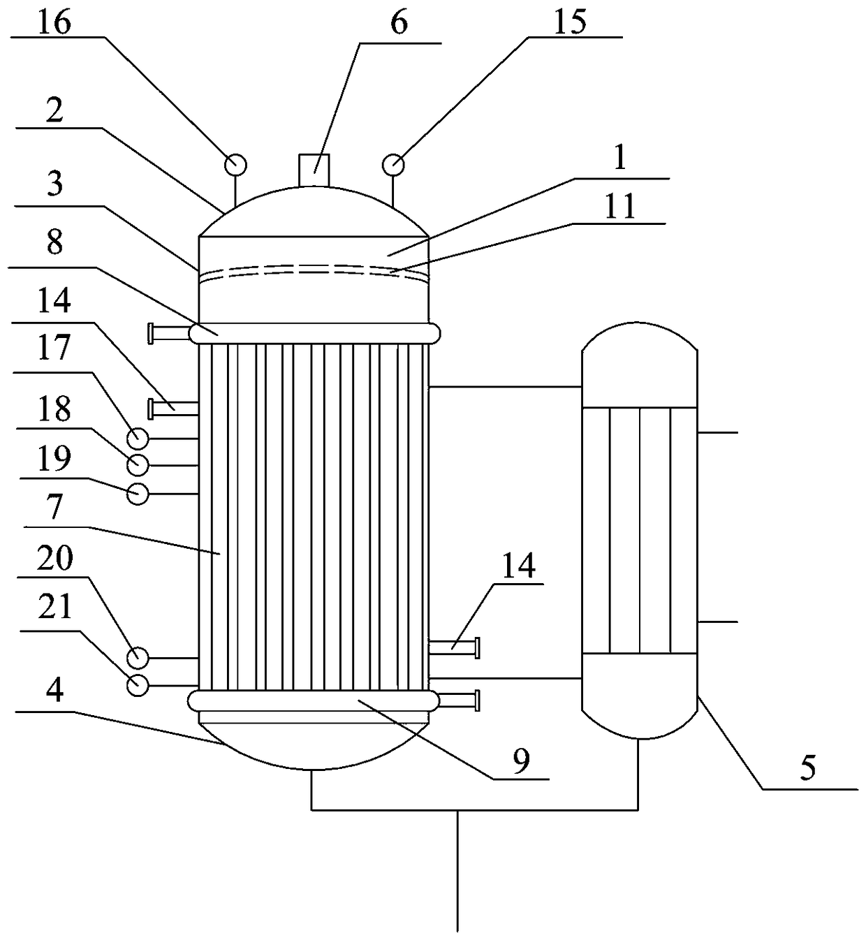
[0021] Such as Figure 1 to Figure 4 As shown, the naphthalene evaporation device in the phthalic anhydride preparation process includes a naphthalene evaporator 1, and the naphthalene evaporator 1 includes an upper head 2, a cylinder 3 and a lower head 4, and the bottom of the cylinder 3 is connected to the naphthalene through a pipeline. The bottom of the reboiler 5, the top of the naphthalene reboiler 5 is connected to the middle and upper part of the cylinder 3, the bottom of the naphthalene reboiler 5 is provided with a heavy component discharge port, and the naphthalene reboiler 5 feeds high-pressure steam to the liquid Naphthalene indirect heating; the top of the upper head 2 is provided with a naphthalene steam outlet 6, the bottom of the lower head 4 is provided with a heavy component discharge port, and the outside of the cylinder 3 is evenly arranged with angle steel 7, and the upper end of the angle steel 7 is connected with The steam inlet passage 8 surrounding th...

Embodiment 2

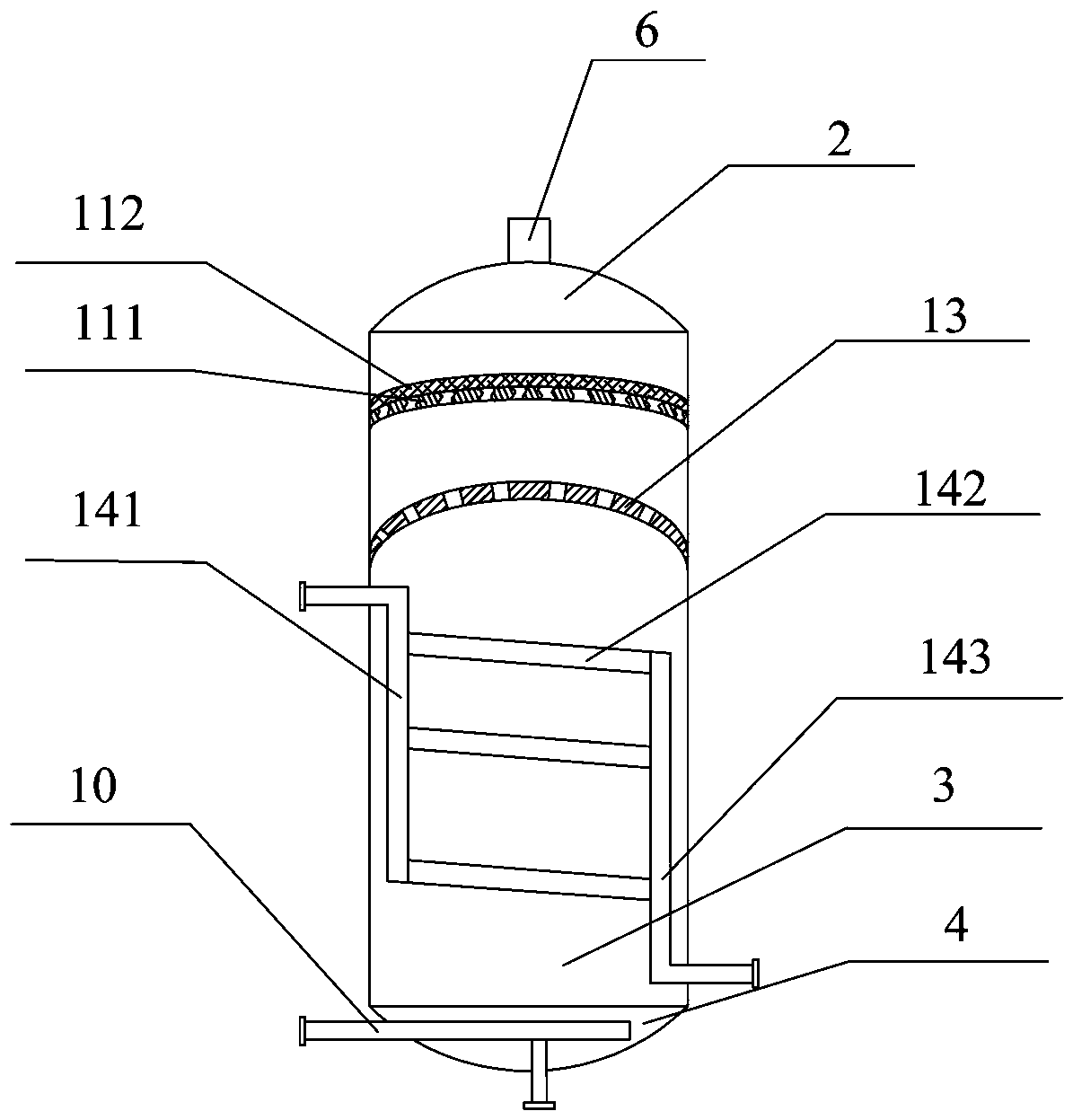
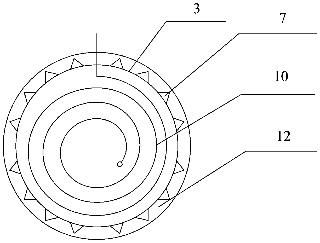
[0023] Such as Figure 1 to Figure 4 As shown, with embodiment 1, the difference is that: the outside of the angle steel 7 is provided with a thermal insulation layer 12; the cylindrical body 3 is provided with a hemispherical retaining plate 13, and the retaining plate 13 is arranged at the position above the liquid naphthalene liquid surface to retain Through holes are evenly arranged on the plate 13; the demister 11 includes a lower primary filter layer 111 and an upper screen layer 112, the primary filter layer 111 is hemispherical, and the primary filter layer 111 is uniformly arranged " S"-shaped channel; the cylinder 3 is provided with a steam heat exchange pipe 14, and the steam heat exchange pipe 14 includes a steam inlet pipe 141, a heat exchange ring pipe 142 and a steam outlet pipe 143, and the heat exchange ring pipe The opposite ends of 142 are respectively connected to the steam inlet pipe 141 and the steam outlet pipe 143, and the heat exchange ring pipe 142 in...


PUM


Abstract

The invention relates to a naphthalene evaporation device used in the preparation process of phthalic anhydride. The naphthalene evaporation device comprises a naphthalene evaporator, the naphthaleneevaporator comprises an upper end enclosure, a cylinder body and a lower end enclosure, the lower part of the cylinder body is connected to the lower part of a naphthalene reboiler through a pipeline,the upper part of the naphthalene reboiler is connected to the middle-upper part of the cylinder body, a heavy component discharge port is formed in the bottom part of the naphthalene reboiler, highpressure steam is introduced into the naphthalene reboiler to indirectly heat the liquid naphthalene; a heavy component discharge port is formed in the bottom part of the lower end enclosure, angle iron is evenly distributed outside the cylinder body, a steam inlet channel encircling the cylinder body is connected to the upper end of the angle iron, a steam outlet channel encircling the cylinder body is connected to the lower end of the angle iron, a closed steam channel is formed among the steam inlet channel, the steam outlet channel, the angle iron and the cylinder body, and a demister is arranged at the upper part of the interior of the cylinder body. The naphthalene reboiler is added to use together with the naphthalene evaporator, the liquid naphthalene is heated, the yielding capacity of the naphthalene is increased, the liquid naphthalene is completely transformed into gas naphthalene, the separation effect is good, and the production and the operation are stable.

Description

technical field [0001] The invention relates to the technical field of chemical equipment, in particular to a naphthalene evaporation device in the preparation process of phthalic anhydride. Background technique [0002] There are relatively many impurities in industrial naphthalene. In the production of phthalic anhydride by naphthalene method, the naphthalene evaporation system is indispensable. It has two functions: (1) to ensure the gasification effect of industrial naphthalene, and to realize the complete vaporization of high-temperature liquid naphthalene into gas naphthalene , to remove the liquid droplets in the steam, the gas naphthalene enters the vaporizer, mixes with air, and enters the oxidizer to react. (2) Industrial naphthalene has many impurities, and high-pressure steam heats liquid naphthalene so that heavy components do not enter the reactor, avoiding excessive temperature and catalyst deactivation. In order not to cause the above situation, the naphthal...

Claims


Application Information

Patent Timeline
Patent Type & Authority Applications(China)
IPC IPC(8): B01D1/00B01D1/30
CPCB01D1/00B01D1/305
Inventor 姚宁李俊华宋广勋杨振苗伟涛
Owner 河南庆安化工高科技股份有限公司
Why Eureka
Try Eureka