Electroplate liquid stirring device

A technology of stirring device and stirring shaft, which is applied to mixers with rotating stirring devices, accessories of mixers, transportation and packaging, etc., can solve the problems of increasing the resistance of stirring, reducing the stirring effect, and not scraping, and reducing the resistance. , Improve stirring efficiency and stirring effect, and enhance the effect of stirring effect

Inactive Publication Date: 2018-08-03
关怡
View PDF7 Cites 15 Cited by
  • Summary
  • Abstract
  • Description
  • Claims
  • Application Information

AI Technical Summary

Problems solved by technology

[0004] However, the above scheme does not scrape off the material adhered to the inner wall of the shell, and the stirring shaft on the stirring rod is easy to adhere to many materials during the rotation process. If it is not removed in time, the resistance of stirring will be increased. , reducing the stirring effect

Method used


Image

  • Electroplate liquid stirring device
  • Electroplate liquid stirring device
  • Electroplate liquid stirring device

Examples


Embodiment Construction

[0020] The present invention will be described in further detail below by means of specific embodiments:

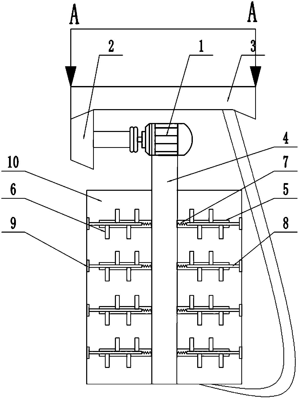
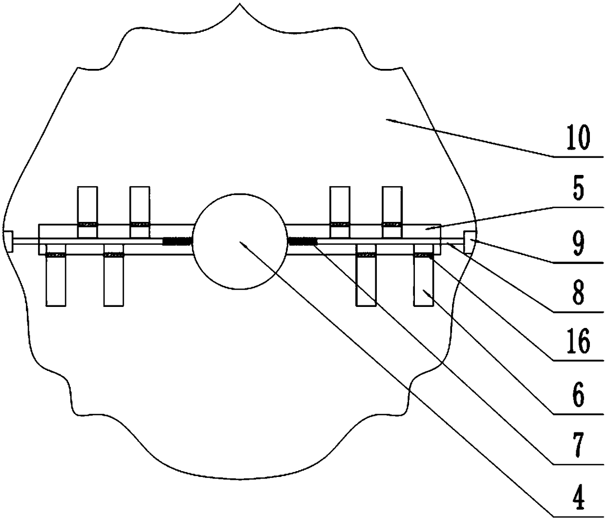
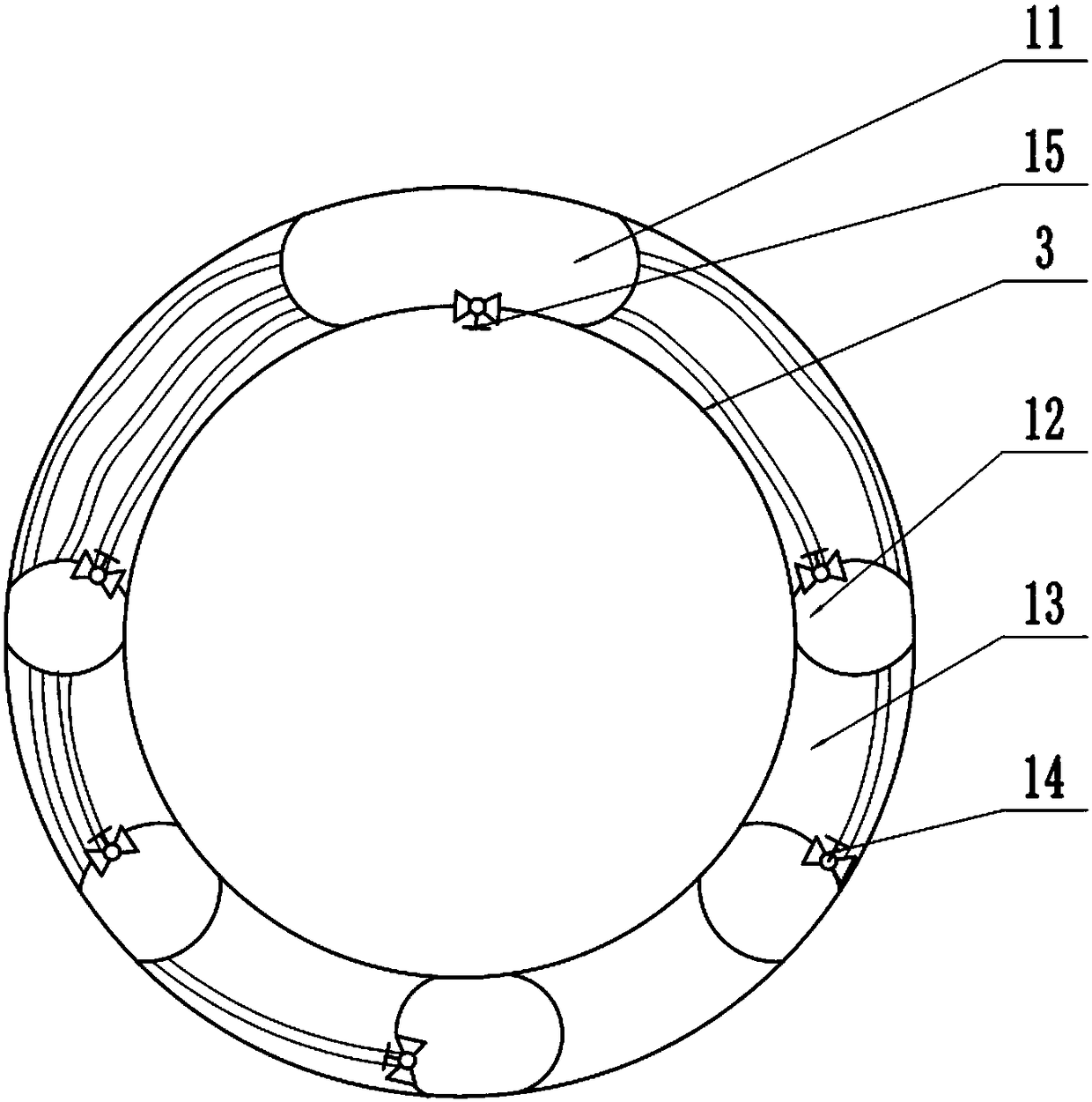
[0021] Instructions attached Figures 1 to 3 The reference signs in include: motor 1, bevel gear 2, gear ring 3, rotating shaft 4, stirring shaft 5, stirring rod 6, spring 7, push rod 8, scraper 9, outer barrel 10, air bag 11, air collection bag 12. Flexible hose 13, air intake one-way valve 14, air outlet one-way valve 15, sealing ring 16.

[0022] Such as figure 1 As shown, a stirring device for electroplating solution includes a frame, an outer barrel 10 and a rotating shaft 4 arranged in the outer barrel 10. The inner wall of the outer barrel 10 is irregularly concave-convex, and the rotating shaft 4 is rotationally connected with a plurality of laterally arranged The stirring shaft 5 is vertically arranged between the stirring shaft 5 and the rotating shaft 4, and a plurality of vertically arranged stirring rods 6 are arranged at intervals on the stirring shaft 5. ...


PUM


Abstract

The invention belongs to the technical field of stirring devices, and particularly discloses an electroplate liquid stirring device. The electroplate liquid stirring device comprises an outer bucket and a spindle, wherein the spindle is rotatably connected with a plurality of stirring shafts, the stirring shafts are provided with a plurality of stirring rods; the inner wall of the outer bucket isof an irregular concave-convex shape; each stirring shaft is of a hollow structure, is provided with a plurality of through holes and is connected with an elastic element; the elastic element is connected with a push rod; the stirring rod and the push rod are hinged to each other; a sealing ring is arranged between the through holes and the stirring rods; the stirring rod and the sealing ring aretightly fit; the upper end of the spindle is connected with a motor; the motor is laterally arranged; the output shaft of the motor is connected with a bevel gear, the upper side of the bevel gear isprovided with a ring gear; the inner part of the ring gear is hollow; the bottom of the ring gear is provided with helical teeth; an air collection bag and an air discharging bag are arranged in the ring gear; the outer wall of the ring gear is provided with an air inlet check valve; one side of the air collection bag is provided with an air outlet check valve; the other end of a hose is in sealing connection with the air discharge bag; one side of the air discharge bag is provided with an air discharge check valve. When the technical scheme of the invention is adopted, the stirring effect andthe stirring efficiency of the electroplate can be improved.

Description

technical field [0001] The invention belongs to the technical field of stirring devices, in particular to an electroplating solution stirring device. Background technique [0002] In the daily production process, the raw material mixing process, as a commonly used production process, is widely used in daily production. Most of the product manufacturing requires the use of stirring devices. At present, many electroplating methods use solution stirring in order to improve the coating quality and operating conditions. The function of stirring the electroplating solution is to continuously update the cathode film, so that a fine coating can be obtained at a high deposition rate. Agitation can also be used in very deep tanks to prevent stratification of the solution and maintain a uniform concentration throughout. At present, the most commonly used stirring methods include mechanical stirring, convective stirring, ultrasonic stirring, etc. Most of the existing mechanical stirr...

Claims


Application Information

Patent Timeline
Patent Type & Authority Applications(China)
IPC IPC(8): B01F7/18B01F11/00B01F13/02B01F15/00B01F33/40
CPCB01F27/054B01F27/0722B01F27/073B01F27/074B01F27/092B01F27/091B01F27/112B01F27/118B01F27/191B01F27/2122B01F27/213B01F31/443B01F31/449B01F33/4021B01F27/90B01F35/123B01F2035/351B01F35/50
Inventor 李志华
Owner 关怡
Why Eureka
Try Eureka