Self-propelled pneumatic pipeline cleaning machine and cleaning method

A technology for pneumatic pipes and cleaning machines, applied in cleaning methods and utensils, chemical instruments and methods, cleaning hollow objects, etc., can solve the problems of heavy equipment, inconvenient operation, poor cleaning effect, etc. Well-designed effects

Active Publication Date: 2018-08-03
陕西祥宇倚天航空科技发展有限公司
View PDF6 Cites 8 Cited by
  • Summary
  • Abstract
  • Description
  • Claims
  • Application Information

AI Technical Summary

Problems solved by technology

[0003] (1) Use the power supply to drive the pipe cleaning head to rotate through the motor, and realize the cleaning of the inner wall of the pipe through the rotational movement of the pipe cleaning head, but the cleaning effect is not good and the position of each cleaning is limited, and the pipe needs to be moved repeatedly to feed, inconvenient operation;
[0004] (2) The pipe cleaning equipment is relatively large in size and heavy, making it inconvenient to move and operate;
[0005] (3) Pipeline cleaning equipment generally only has the cleaning head extended into the pipeline for cleaning, and the drive that drives the cleaning head cannot enter the inner wall of the pipeline because of its large volume, so it is inconvenient to clean a long pipeline;
[0006] (4) The brush used in the current pipeline cleaning equipment only imitates manual scrubbing along the axis of the inner wall of the pipeline, and the brush cannot form a positive pressure on the inner wall of the pipeline to be cleaned, making the cleaning effect poor

Method used


Image

  • Self-propelled pneumatic pipeline cleaning machine and cleaning method
  • Self-propelled pneumatic pipeline cleaning machine and cleaning method
  • Self-propelled pneumatic pipeline cleaning machine and cleaning method

Examples


Embodiment Construction

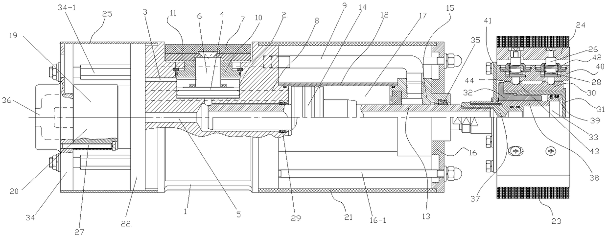
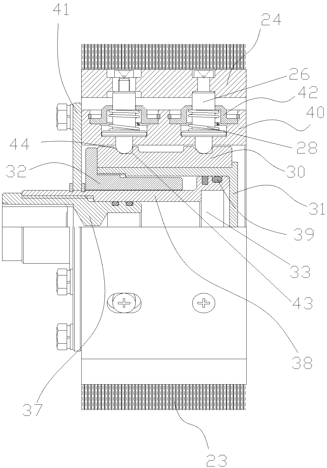
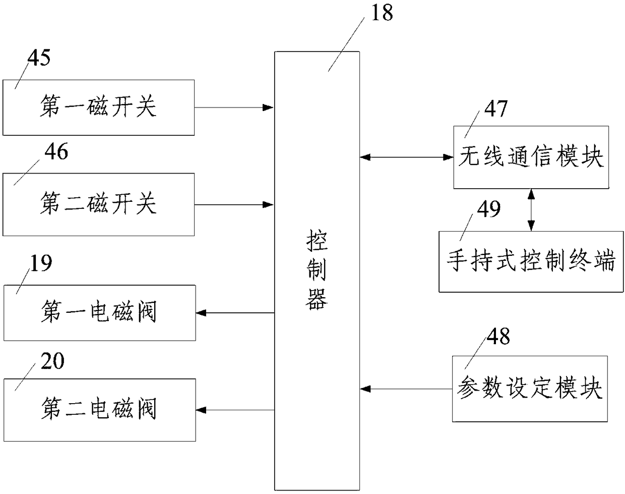
[0067] Such as figure 1 , figure 2 and image 3 As shown, the self-propelled pneumatic pipeline cleaning machine of the present invention includes a pipeline cleaning mechanism that is arranged inside the pipeline to be cleaned and cleans the inner wall of the pipeline to be cleaned, and a monitoring device that monitors the pipeline cleaning mechanism. The pipeline cleaning mechanism includes A guide plate 22 for compressed gas to pass through, a braking mechanism fixedly connected to the guide plate 22 on one side, a cleaning head mechanism installed on the other side of the braking mechanism, and driving the cleaning head mechanism along the inner wall of the pipeline to be cleaned A reciprocating drive mechanism for reciprocating movement, the brake mechanism includes a brake housing 1 fixedly connected to the guide plate 22 on one side, a plurality of brake housings 1 uniformly arranged along the circumferential direction and can be in close contact with the inner wall ...


PUM


Abstract

The invention discloses a self-propelled pneumatic pipeline cleaning machine and cleaning method. The cleaning machine comprises a pipeline cleaning mechanism and a monitoring device; the pipeline cleaning mechanism comprises a guiding plate, a braking mechanism, a cleaning head mechanism and a reciprocating driving mechanism; and the monitoring device comprises a controller, a first magnetic switch, a second magnetic switch, a first electromagnetic valve and a second electromagnetic valve. The cleaning method includes the steps that firstly, the self-propelled pneumatic pipeline cleaning machine is placed; secondly, the braking mechanism performs braking and the cleaning head mechanism performs radial expanding; thirdly, the inner wall of a pipeline is cleaned; and fourthly, when cleaningof the whole to-be-cleaned pipeline is completed, and the self-propelled pneumatic pipeline cleaning machine is taken out. The self-propelled pneumatic pipeline cleaning machine is simple in structure, capable of easily, conveniently and fast cleaning the inner wall of the pipeline and good in cleaning effect.

Description

technical field [0001] The invention belongs to the technical field of pipeline cleaning, and in particular relates to a self-propelled pneumatic pipeline cleaning machine and a cleaning method. Background technique [0002] Circular metal pipes are widely used in engineering and construction. Although circular metal pipes have been cleaned and oil-sealed at the factory. However, before processing or laying on site, the debris accumulated in the circular metal pipe during transportation and storage must be cleaned or the oil seal must be removed. Therefore it is very difficult to clean the inner wall of the circular metal pipe before laying. At present, most of the pipes are cleaned manually, which is not only laborious, labor-intensive, time-consuming, but also has low cleaning efficiency. With the development of technology, pipeline cleaning equipment that uses mechanized means to replace manual cleaning has emerged, but the current pipeline cleaning equipment still has ...

Claims


Application Information

Patent Timeline
Patent Type & Authority Applications(China)
IPC IPC(8): B08B9/04
CPCB08B9/04
Inventor 莫文炜董春玉
Owner 陕西祥宇倚天航空科技发展有限公司
Why Eureka
Try Eureka