Gas-assisted resistance spot welding device and its cooling and heating method

A resistance spot welding and gas-assisted technology, used in auxiliary devices, resistance welding equipment, auxiliary welding equipment, etc. Welding method, not using popularization, not suitable for spot welding, etc., to achieve the effect of wide range of use, easy popularization and application, and uniform cooling effect

Active Publication Date: 2020-07-14
SHANGHAI JIAOTONG UNIV
View PDF14 Cites 0 Cited by
  • Summary
  • Abstract
  • Description
  • Claims
  • Application Information

AI Technical Summary

Problems solved by technology

However, due to structural limitations, these methods are only suitable for welding methods such as submerged arc welding, gas shielded welding, argon arc welding, electroslag welding or circular welding, and are not suitable for spot welding.
And the cost is relatively high, do not use to promote the use of

Method used


Image

  • Gas-assisted resistance spot welding device and its cooling and heating method
  • Gas-assisted resistance spot welding device and its cooling and heating method
  • Gas-assisted resistance spot welding device and its cooling and heating method

Examples


Embodiment 1

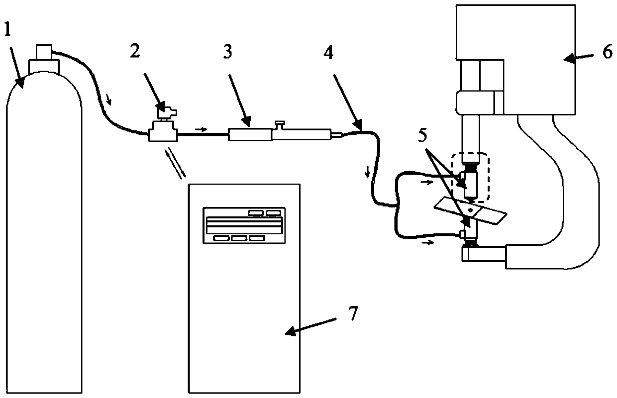
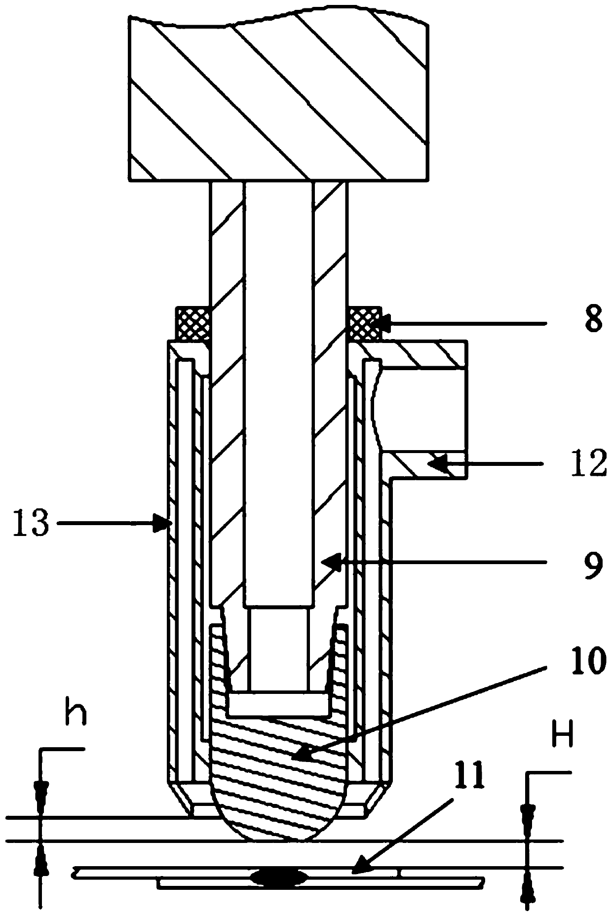
[0051] like figure 1 and figure 2 As shown, this embodiment includes: a gas cylinder 1, a solenoid valve 2, a vortex tube 3, a gas pipeline 4, a nozzle 5, a resistance spot welding system 6, a control system 7, a nozzle fixing device 8, an electrode rod 9, and an electrode cap 10 and workpiece 11. Wherein: the resistance spot welding system 6 is connected with the control system 7 and transmits welding control signals, the control system 7 is connected with the solenoid valve 2 and controls the startup and closing of the solenoid valve 2, when the solenoid valve 2 is started, the gas in the gas cylinder 1 can pass through The cold air end of the solenoid valve 2 and the scroll tube 3 enters the nozzle 5. The workpiece 11 is fixed on the clamping device. figure 2 Yes figure 1 A partial enlarged view of the inner part of the middle dashed frame, the nozzle 5 is connected with the nozzle fixing device 8 by screws or snaps, and is fixed on the electrode rod 9 by the nozzle f...

Embodiment 2

[0063] In this embodiment, the upper metal plate is aluminum alloy AA6061-T6, the lower metal plate is galvanized dual-phase steel plate DP590, the thickness of the plate is 1.2mm, the aluminum plate is mechanically polished to remove the oxide layer on the surface, and the metal plate is removed by acetone Oil stains on the surface.

[0064] Process parameters: welding current is 8kA, welding time is 160ms, electrode pressure is 3.5kN, pre-pressure time is 100ms, pressure holding time is 200ms, argon gas is used as cooling gas, its flow rate is 20L / min, and the inlet pressure is 5.5bar. Other parameters are the same as in Example 1.

[0065] In this embodiment, due to the welding of dissimilar metals, the physical properties such as hardness, melting point and thermal conductivity of the two metals are different. The upper and lower plates can be cooled with different degrees. After the gas comes out of the gas cylinder, it is divided into two paths. Solenoid valves and cool...

Embodiment 3

[0073] The system can also be used for auxiliary heating of welding workpieces.

[0074] The upper and lower metal plates of this embodiment are all DP980 dual-phase steel, the thickness of the plate: 1.2 mm, and the oil stain on the surface of the metal plate is removed with acetone reagent.

[0075] Process parameters: welding current is 7.5kA, welding time is 200ms, electrode pressure is 4kN, preload time is 100ms, pressure holding time is 200ms, argon gas is used as cooling gas, and its flow rate is 20L / min, and other parameters are the same as in Example 1.

[0076] The difference between the components of this embodiment and the first embodiment is that the outlet gas of the hot gas end of the vortex tube 3 is used as the auxiliary gas.

[0077] The welding process of this embodiment is as follows Figure 8 As shown in (a) to (f):

[0078] 1) Place the metal plate on top of another metal plate and clamp it by the clamping device;

[0079] 2) The welding torch moves to...


PUM


Abstract

The invention discloses a gas auxiliary resistance spot welding device and a cooling and heating method thereof. The device comprises a resistance spot welding system, a gas auxiliary system and a control system; the gas auxiliary system is connected with the resistance spot welding system; the control system is correspondingly in communication with the gas auxiliary system and the resistance spotwelding system; the gas auxiliary system comprises a gas cylinder, an electromagnetic valve, a vortex tube, a gas circuit tube and nozzles which are connected in sequence; and the nozzles are connected with the resistance spot welding system, the number of the nozzles is two, and the two nozzles are oppositely arranged. The electric resistance spot welding device has the beneficial effects that the cooling effect can be provided for a joint in the resistance spot welding process, the joint can be heated, and the application range is wider. Compared with an existing follow-up cooling method for submerged arc welding, argon arc welding and the like, the device can be applied to a spot welding process through reasonable design, low-temperature gas cooling is applied to the front surface of the spot welding joint, so that the cooling effect is more uniform, and the system can accurately control the cooling start-up time, the air flow intensity and the gas temperature.

Description

technical field [0001] The invention relates to a method in the technical field of single-point connection of thin-plate materials, in particular to a gas-assisted resistance spot welding device capable of assisted cooling or heating of spot welding joints during the process of resistance spot welding of plates and the same Cooling and heating methods. Background technique [0002] Resistance spot welding is to press the workpiece to be welded between the two electrodes in the form of lap joint, and pass a large current to melt the plate by using the heat generated by the contact resistance of the joint surface of the plate. The distance between the metal atoms of the bonding surface reaches the lattice distance to form a metal bond, thereby forming a welding method for solder joints. Because of its high welding efficiency, low cost, easy automation and no harmful gas generation, resistance spot welding process is a reliable method for sheet assembly in machine manufacturin...

Claims


Application Information

Patent Timeline
Patent Type & Authority Patents(China)
IPC IPC(8): B23K11/11B23K11/36B23K37/00
CPCB23K11/11B23K11/36B23K37/003
Inventor 冯巧波李永兵来新民
Owner SHANGHAI JIAOTONG UNIV
Why Eureka
Try Eureka