
Steel plate surface efficient grinding and rust removing device

A high-efficiency, high-efficiency steel plate technology, applied in the direction of grinding drive devices, grinding machines, grinding frames, etc., can solve the problems of poor rust removal effect and low steel plate grinding efficiency, and achieve efficient and rapid rust removal, significant rust removal effect, Effect of Relative Displacement Increase

Inactive Publication Date: 2018-08-03
王芳
View PDF6 Cites 15 Cited by
  • Summary
  • Abstract
  • Description
  • Claims
  • Application Information

AI Technical Summary

Problems solved by technology

[0003] In the process of steel plate processing, according to the requirements of steel plate processing technology and actual steel plate use requirements, it is necessary to grind and derust the surface of the steel plate. The current steel plate grinding and derusting device has a low grinding efficiency for the steel plate, resulting in poor derusting effect

Method used


Image

  • Steel plate surface efficient grinding and rust removing device
  • Steel plate surface efficient grinding and rust removing device
  • Steel plate surface efficient grinding and rust removing device

Examples


Embodiment Construction

[0021] Below in conjunction with specific embodiment, the technical scheme of this patent is described in further detail:

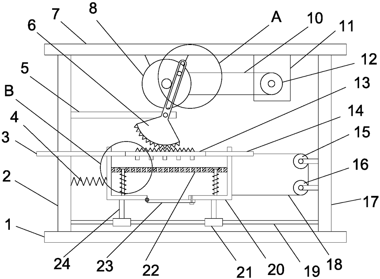
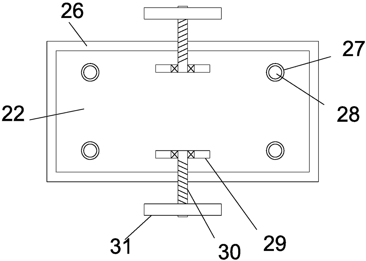
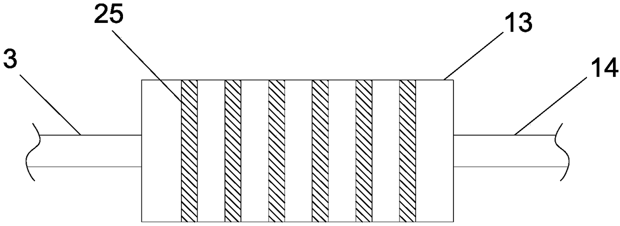
[0022] see Figure 1-5 , a high-efficiency grinding and derusting device for steel plate surfaces, comprising a base plate 1, a left vertical plate 2 and a right vertical plate 17 are vertically fixedly installed on the bottom plate 1, and a top plate 7 is fixedly installed horizontally on the top of the left vertical plate 2 and the right vertical plate 17, Between the left vertical plate 2 and the right vertical plate 17, the limit guide rod 19 is fixedly installed horizontally, and the sliding sleeve on the limit guide rod 19 is provided with a sliding sleeve 21, and the vertical fixed support column 24 is installed on the sliding sleeve 21. A collecting tank 20 is fixedly installed on the post 24, and a bearing plate 22 is slidably arranged in the collecting tank 20. A sliding shaft 35 that slides and runs through the collecting tank 20 is vertically ...


PUM


Abstract

The invention discloses a steel plate surface efficient grinding and rust removing device. The device comprises a bottom plate, wherein a left vertical plate and a right vertical plate are verticallyand fixedly arranged on the bottom plate, a top plate is horizontally and fixedly arranged at the tops of the left vertical plate and the right vertical plate, and a limiting guide rod is horizontallyand fixedly installed between the left vertical plate and the right vertical plate; sliding sleeves sleeve the limiting guide rod in a sliding mode, and supporting columns are vertically and fixedlyinstalled on the sliding sleeves. According to the steel plate surface efficient grinding and rust removing device, the left-and-right and back-and-forth movement of a transmission plate is realized through clockwise and anticlockwise alternate rotation of a fan-shaped teeth, and then grinding strips are driven to carry out back-and-forth grinding on the surface of a steel plate; meanwhile, a pullrope pulls a collecting groove to achieve all reciprocating motion under the elastic acting force of a reset spring, so that the steel plate is driven to move in the left-and-right direction and theback-and-forth direction, the steel plate always moves back to the grinding strips, the relative displacement of the steel plate and the grinding strips is greatly increased, and rust removal of the steel plate is more efficient and rapid; and a bearing plate and the grinding strips clamp the steel plate under the elastic action of damping springs, so that the rust removing quality of the steel plate is effectively improved, and the rust removing effect is remarkable.

Description

technical field [0001] The invention relates to the technical field of steel plate derusting, in particular to a high-efficiency grinding and derusting device for steel plate surfaces. Background technique [0002] The steel plate is a flat steel material that is poured with molten steel and pressed after cooling. Steel plates are classified according to thickness, thin steel plates < 4 mm and the thinnest 0.2 mm, thick steel plates 4-60 mm, and extra-thick steel plates 60-115 mm. Steel plates are divided into hot-rolled and cold-rolled according to rolling. The width of the thin plate is 500~1500 mm; the width of the thick plate is 600~3000 mm. Sheets are classified by steel type, including ordinary steel, high-quality steel, alloy steel, spring steel, stainless steel, tool steel, heat-resistant steel, bearing steel, silicon steel, and industrial pure iron sheets, etc.; by professional use, there are plates for oil drums, Enamel plates, bulletproof plates, etc.; accor...

Claims


Application Information

Patent Timeline
IPC IPC(8): B24B27/04B24B7/02B24B47/04B24B41/06B24B41/02
CPCB24B27/04B24B7/02B24B41/02B24B41/068B24B47/04
Inventor 王芳
Owner 王芳
Learn More