Motor control center electric power distribution cabinet machining equipment

A control center and processing equipment technology, applied in the direction of conveyor objects, transportation and packaging, etc., can solve problems such as failure to use normally, easy slipping of power distribution cabinets, instability of power distribution cabinets, etc., to avoid slip damage and work stability good, time-saving effect

Inactive Publication Date: 2018-08-03
陈秀兰
View PDF0 Cites 5 Cited by
  • Summary
  • Abstract
  • Description
  • Claims
  • Application Information

AI Technical Summary

Problems solved by technology

[0003] In order to solve the above problems, the present invention provides a processing equipment for electric power distribution cabinets in motor control centers, which can solve the need to manually transport the power distribution cabinets into the packing box with the help of existing equipment during the packaging process of the existing power distribution cabinets. It is necessary to manually fix the power distribution cabinet with tools such as ropes. For power distribution cabinets of different specifications, it is necessary to manually adjust the binding ropes. The operation is complicated and time-consuming. The power distribution cabinet is easy to slip, so that the deformation of the power distribution cabinet cannot be used normally, the labor intensity is high, and the work efficiency is low. It can realize the stable clamping function of the power distribution cabinet during the packaging process, without manual operation, and will not make the power distribution cabinet Slip and deform, and has the advantages of good working stability, time saving, simple operation, low labor intensity and high work efficiency

Method used


Image

  • Motor control center electric power distribution cabinet machining equipment
  • Motor control center electric power distribution cabinet machining equipment
  • Motor control center electric power distribution cabinet machining equipment

Examples


Embodiment Construction

[0015] In order to make the technical means, creative features, goals and effects achieved by the present invention easy to understand, the present invention will be further described below in conjunction with specific illustrations.

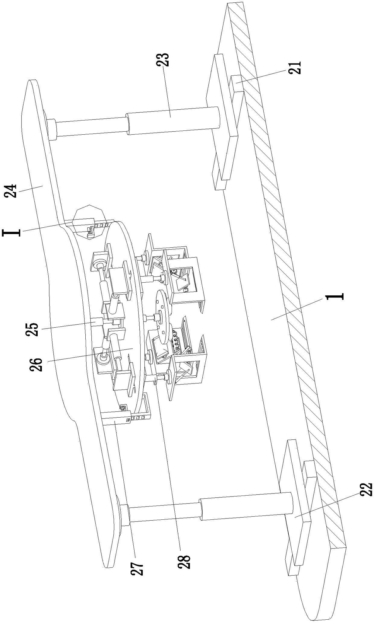
[0016] like Figure 1 to Figure 3As shown, a motor control center power distribution cabinet processing equipment includes a base plate 1 on which two clamping electric sliders 21 are installed, and the two clamping electric sliders 21 are symmetrically installed on the left and right sides of the base plate 1 , a clamping mobile plate 22 is installed on the clamping electric slider 21, a clamping telescopic cylinder 23 is installed on the clamping mobile plate 22, and the top of the clamping telescopic cylinder 23 is installed on the clamping support plate 24 through a flange. The lower end of the holding support plate 24 is equipped with a clamping lifting cylinder 25, and the top of the clamping lifting cylinder 25 is installed on the clampin...


PUM


Abstract

The invention relates to motor control center electric power distribution cabinet machining equipment which comprises a bottom plate; two clamping electric sliding blocks are arranged on the bottom plate, and are symmetrically arranged on the left side and the right side of the bottom plate; clamping moving plates are arranged on the clamping electric sliding blocks; clamping telescopic air cylinders are arranged on the clamping moving plates; the top ends of the clamping telescopic air cylinders are arranged at a clamping supporting plate through flanges; a clamping lifting air cylinder is arranged at the lower end of the clamping supporting plate; and the top end of the clamping lifting air cylinder is arranged on a clamping lifting plate through a flange. The problems that manual work is required for carrying an existing power distribution cabinet into a packaging box by virtue of existing equipment in the packaging process of the existing power distribution cabinet, the manual workis required for fixing the power distribution cabinet by virtue of tools like a rope, the manual work is required for adjusting binding ropes with respect to the power distribution cabinets in different sizes, the operation is complicated, time and labor are consumed, and the power distribution cabinet is not bound stably by the manual work by virtue of the rope can be solved.

Description

technical field [0001] The invention relates to the technical field of packaging equipment for power distribution cabinets, in particular to processing equipment for power distribution cabinets in motor control centers. Background technique [0002] Power distribution cabinets are divided into power distribution cabinets, lighting distribution cabinets, and metering cabinets, and are the final equipment of the power distribution system. The power distribution cabinet is a general term for the motor control center. The power distribution cabinet is used in the occasions where the load is relatively scattered and there are few circuits; the motor control center is used in the occasions where the load is concentrated and there are many circuits. They distribute the electric energy of a certain circuit of the upper-level power distribution equipment to the nearest load. This level of equipment should provide protection, monitoring and control for the load. Various protective d...

Claims


Application Information

Patent Timeline
Patent Type & Authority Applications(China)
IPC IPC(8): B65G47/91
CPCB65G47/91
Inventor 陈秀兰
Owner 陈秀兰
Why Eureka
Try Eureka