Tension setting method for vertical continuous annealing furnace

A technology of continuous annealing furnace and setting method, which is applied in the field of iron and steel smelting, and can solve problems such as strip steel is easy to deviate, achieve the effects of no deviation, solve scratches in the strip steel furnace, and ensure quality

Active Publication Date: 2018-08-03
SHOUGANG JINGTANG IRON & STEEL CO LTD
View PDF7 Cites 13 Cited by
  • Summary
  • Abstract
  • Description
  • Claims
  • Application Information

AI Technical Summary

Problems solved by technology

[0007] The embodiment of the present application provides a method for setting the tension of the vertical continuous annealing furnace, which solves the technical problem that the strip steel tends to deviate in the vertical continuous annealing furnace in the prior art, so that the strip steel can can run stably in

Method used


Image

  • Tension setting method for vertical continuous annealing furnace
  • Tension setting method for vertical continuous annealing furnace
  • Tension setting method for vertical continuous annealing furnace

Examples


Embodiment 1

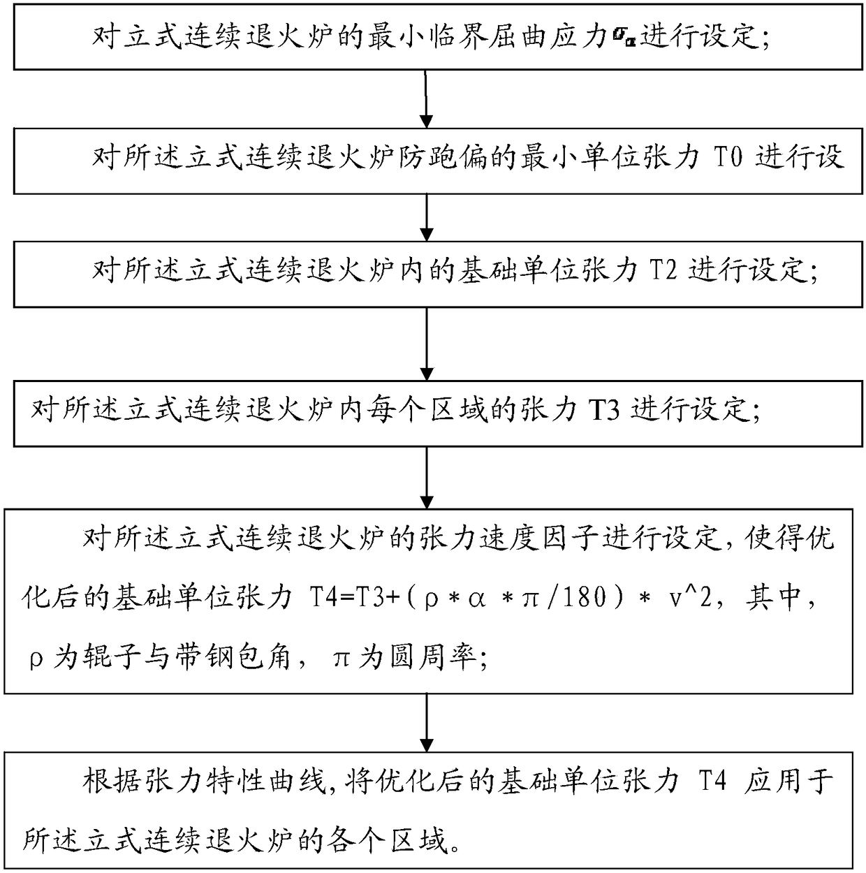
[0033] Such as figure 1 As shown, the embodiment of the present invention provides a method for setting the tension of a vertical continuous annealing furnace, including:

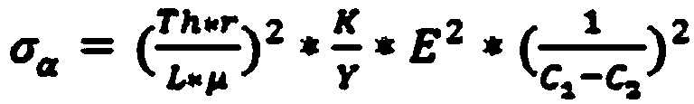
[0034] Step S1: The minimum critical buckling stress σ of the vertical continuous annealing furnace α make settings;

[0035] Step S2: setting the minimum unit tension T0 for preventing deviation of the vertical continuous annealing furnace;

[0036] Step S3: Set the basic unit tension T2 in the vertical continuous annealing furnace; the basic unit tension T2 satisfies F*T0α ), where K is the safety factor against bending, and F is the safety factor against deviation.

[0037] Step S4: Set the tension T3 of each area in the vertical continuous annealing furnace; make the tension T3 of each area satisfy T3=T2*F, where F is the safety factor for preventing deviation.

[0038] Step S5: Set the tension speed factor of the vertical continuous annealing furnace so that the optimized basic unit tension T4=T3+(ρ...

Embodiment 2

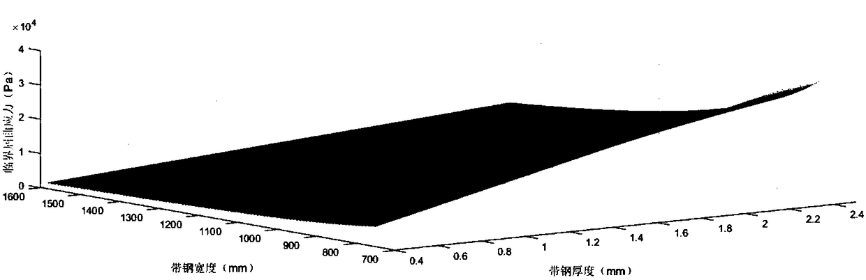
[0068] For example, SGJT2230CAL produces AQ89900R with a specification of 2.0*1600mm. Among them, the carbon equivalent is greater than 0.1, the annealing temperature is greater than 830°C, and the operating speed of the furnace area is 310m / min. Select 10# furnace roll in the heating section, the main parameters are as follows: furnace roll diameter 900mm, friction coefficient 0.025, strip steel high temperature yield strength 1.0E+7Pa Pa, elastic modulus 1.17E+11Pa, top and bottom roller distance 19m. The critical buckling stress σ of different specifications is obtained α ,Such as figure 2 shown.

[0069] In this embodiment, the annealing temperature is selected at 820-840°C, according to F*T0α ) to obtain the basic unit tension tables of different specifications, as shown in Table 2. Wherein T0=1.9Mpa, F: anti-deviation safety factor 1.57 (1.2-1.6) K: anti-deviation safety factor 1.23 (1.2-1.4), W in Table 2 is strip width, t is strip thickness.

[0070] Table 2: Tens...


PUM


Abstract

The invention discloses a tension setting method for a vertical continuous annealing furnace. The tension setting method comprises the following steps of: setting the minimum critical buckling stressSigma Alpha of the vertical continuous annealing furnace; setting the minimum unit tension T0 for preventing running deflection of the vertical continuous annealing furnace; setting the basic unit tension T2 inside the vertical continuous annealing furnace; setting the tension T3 of each region inside the vertical continuous annealing furnace; setting the tension speed factor of the vertical continuous annealing furnace to make sure that the optimized basic unit tension T4=T3+(sigma*alpha*pi / 180)*v^2; and applying the optimized basic unit tension T4 to each region of the vertical continuous annealing furnace according to a tension characteristic curve. The tension setting method for the vertical continuous annealing furnace disclosed by the invention solves the technical problem that running deflection of band steel inside the vertical continuous annealing furnace is easily caused in the prior art, and thus the band steel can stably run inside the vertical continuous annealing furnace.

Description

technical field [0001] The invention relates to the technical field of iron and steel smelting, in particular to a tension setting method of a vertical continuous annealing furnace. Background technique [0002] From the 1940s to the mid-1950s, with the continuous deepening of the basic theory of continuous heat treatment metallurgy, the number of continuous heat treatment units has increased, and the speed of the units has also increased to 250-300m / min. From the mid-1950s to the end of the 1960s, the unit speed increased to 450-600m / min. Since then, how to run the annealing furnace at high speed, continuously and stably (stable through the plate) has become a bottleneck problem that plagues the unit. [0003] The main factors affecting the stable operation of the strip steel furnace are deviation and bending. Because of tension setting or control abnormality, strip deviation and buckling occur from time to time. According to the analysis of unplanned opening of the furna...

Claims


Application Information

Patent Timeline
Patent Type & Authority Applications(China)
IPC IPC(8): C21D1/26C21D9/56C21D11/00
CPCC21D1/26C21D9/564
Inventor 任伟超郑晓飞马晓宁祖艳萍张学范王晓广王道金林英哲张阳阳巫雪松任秋红
Owner SHOUGANG JINGTANG IRON & STEEL CO LTD
Why Eureka
Try Eureka