Electric control fan control method of automobile, control device and automobile

A fan control and control method technology, applied in the direction of coolant flow control, measuring device, engine cooling, etc., can solve the problem of slow thawing speed of the post-processing system

Active Publication Date: 2018-08-03
WEICHAI POWER CO LTD
View PDF10 Cites 2 Cited by
  • Summary
  • Abstract
  • Description
  • Claims
  • Application Information

AI Technical Summary

Problems solved by technology

[0004] However, when the vehicle is in a cold region, controlling the electronically controlled fan according to t

Method used


Image

  • Electric control fan control method of automobile, control device and automobile
  • Electric control fan control method of automobile, control device and automobile
  • Electric control fan control method of automobile, control device and automobile

Examples


Embodiment 1

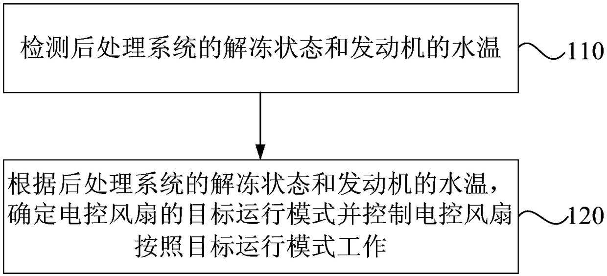
[0039] figure 1 It is a flow chart of a method for controlling an electronically controlled fan of a car provided in Embodiment 1 of the present invention. The car includes an aftertreatment system and an engine. It can be performed by the electronically controlled fan control device of the car, and the control method includes:

[0040] Step 110, detecting the unfreezing state of the aftertreatment system and the water temperature of the engine.

[0041] Wherein, the water temperature of the engine refers to the temperature of the engine coolant.

[0042] Specifically, the automobile includes an aftertreatment system and an engine. The engine and the aftertreatment system are provided with cooling pipes for the circulation of the coolant. The coolant is stored in the engine water tank. medium circulation. The post-treatment system includes a urea tank, which is equipped with an aqueous urea solution. When the ambient temperature is about minus 11 degrees Celsius, the aqueou...

Embodiment 2

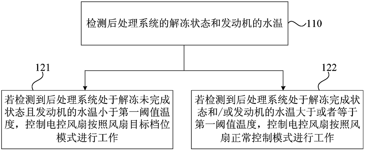
[0052] figure 2 It is a flow chart of a method for controlling an electronically controlled fan of a vehicle provided by Embodiment 2 of the present invention. On the basis of the above-mentioned Embodiment 1, this embodiment further provides an optional method for controlling an electronically controlled fan of a vehicle.

[0053] Optionally, step 120 provided in the first embodiment above is to determine the target operating mode of the electronically controlled fan and control the electronically controlled fan to work in accordance with the target operating mode according to the thawing state of the aftertreatment system and the water temperature of the engine, specifically including:

[0054] Step 121. If it is detected that the post-processing system is in the unfreezing state and the water temperature of the engine is lower than the first threshold temperature, control the electronically controlled fan to work according to the fan target gear mode;

[0055] Step 122: If...

Embodiment 3

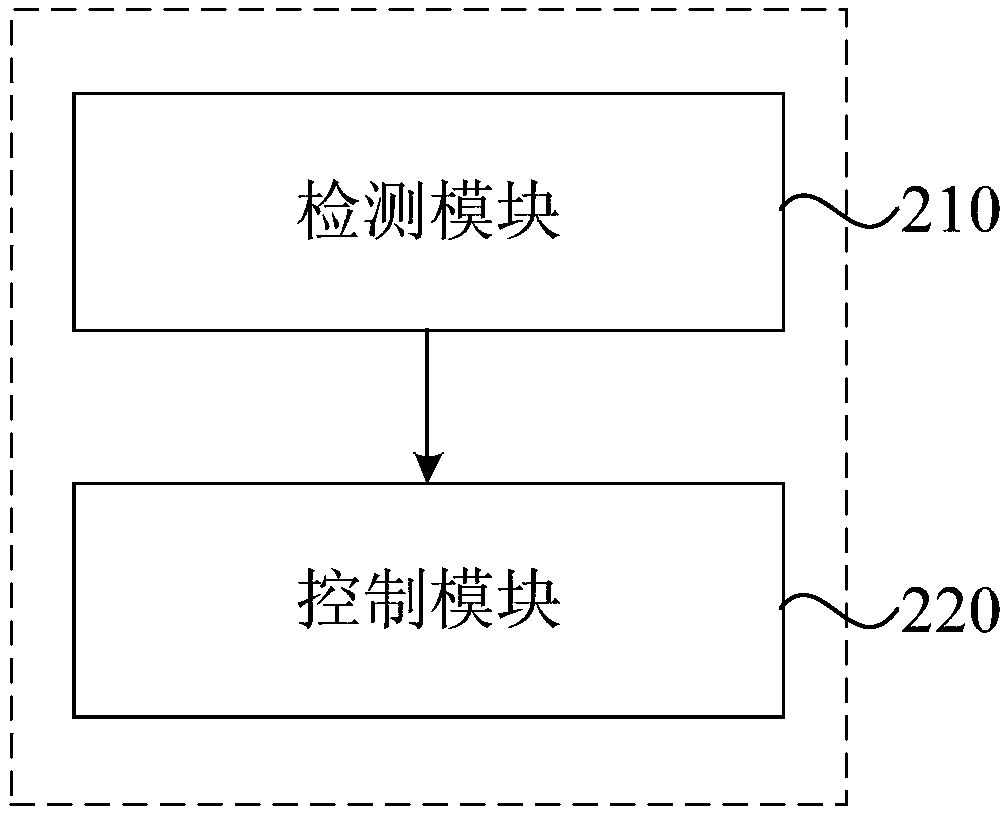
[0070] image 3 Shown is a schematic structural diagram of the electronically controlled fan control device for a car provided by Embodiment 3 of the present invention. The car includes an aftertreatment system and an engine. This embodiment is applicable to the control of the electric fan when the car is in a cold region. The device can execute the method for controlling the electronically controlled fan of a car provided in any of the above embodiments, and the control device includes:

[0071] A detection module 210, configured to detect the unfreezing state of the aftertreatment system and the water temperature of the engine;

[0072] The control module 220 is used to determine the target operating mode of the electronically controlled fan and control the electronically controlled fan to work according to the target operating mode according to the defrosting state of the aftertreatment system and the water temperature of the engine.

[0073] Optionally, the operation mode...


PUM


Abstract

The invention discloses an electric control fan control method of an automobile, a control device and the automobile. The automobile comprises a post-processing system and an engine. The control method comprises the following steps of detecting the unfreezing state of the post-processing system and the water temperature of the engine; and according to the unfreezing state of the post-processing system and the water temperature of the engine, determining the target operation mode of an electric control fan, and controlling the electric control fan to work according to the target operation mode.According to the electric control fan control method, the electric control fan can be controlled according to the unfreezing state of the post-processing system, and the unfreezing speed of the post-processing system of the automobile under the cold condition is accelerated, and the problem that the unfreezing speed of the vehicle post-processing system is low when a vehicle is in a cold region is solved.

Description

technical field [0001] The embodiment of the present invention relates to the defrosting technology of the post-processing system, and in particular to a method for controlling an electronically controlled fan of an automobile, a control device, and the automobile. Background technique [0002] Urea tanks and urea pumps in automotive aftertreatment systems are prone to freezing in cold regions. [0003] Electronically controlled fans are widely used in the cooling system of automobiles. The operation of the electronically controlled fan on the existing vehicle is based on the engine water temperature as the judgment standard. When the engine electronic control unit detects that the engine water temperature reaches the preset temperature, the electronically controlled fan is controlled to operate, thereby promoting the heat dissipation of the engine. [0004] However, when the vehicle is in a cold region, controlling the electronically controlled fan according to the existin...

Claims


Application Information

Patent Timeline
IPC IPC(8): F01P7/02
CPCF01N2610/1486F01P7/02F01P2025/08F01P2050/22
Inventor 陈月春王长通吕文芝张小田朱江苏
Owner WEICHAI POWER CO LTD
Why Eureka
Try Eureka