Orthogonal magnetic circuit radial-axial-integrated magnetic bearing based on symmetrical self-lubricating flexible backup bearing structure

A magnetic suspension bearing and auxiliary bearing technology, which is applied to magnetic bearings, bearings, shafts and bearings, etc., can solve the problems of reducing the rigidity mode of the rotor, scrapping the high-speed magnetic suspension motor, and blocking the auxiliary bearing, so as to avoid the high heat phenomenon and avoid the whole system. Machine scrapped, improve the effect of rigid mode

Active Publication Date: 2018-08-03
BEIHANG UNIV
View PDF11 Cites 4 Cited by
  • Summary
  • Abstract
  • Description
  • Claims
  • Application Information

AI Technical Summary

Problems solved by technology

[0005] 1. Since the magnetic suspension bearing stator and the auxiliary bearing are respectively fixed on different parts, it is difficult for the magnetic suspension bearing stator and the auxiliary bearing to meet the high coaxiality requirements, and then the magnetic gap and the auxiliary bearing are asymmetrical, so that the control system is very difficult. Difficult to achieve high-precision control of magnetic suspension bearings
[0006] 2. When the high-speed maglev rotor loses stability, it will collide violently with the auxiliary bearing. Due to the high rigidity and low damping of the traditional mechanical bearing, the balls o

Method used


Image

  • Orthogonal magnetic circuit radial-axial-integrated magnetic bearing based on symmetrical self-lubricating flexible backup bearing structure
  • Orthogonal magnetic circuit radial-axial-integrated magnetic bearing based on symmetrical self-lubricating flexible backup bearing structure
  • Orthogonal magnetic circuit radial-axial-integrated magnetic bearing based on symmetrical self-lubricating flexible backup bearing structure

Examples


Embodiment 1

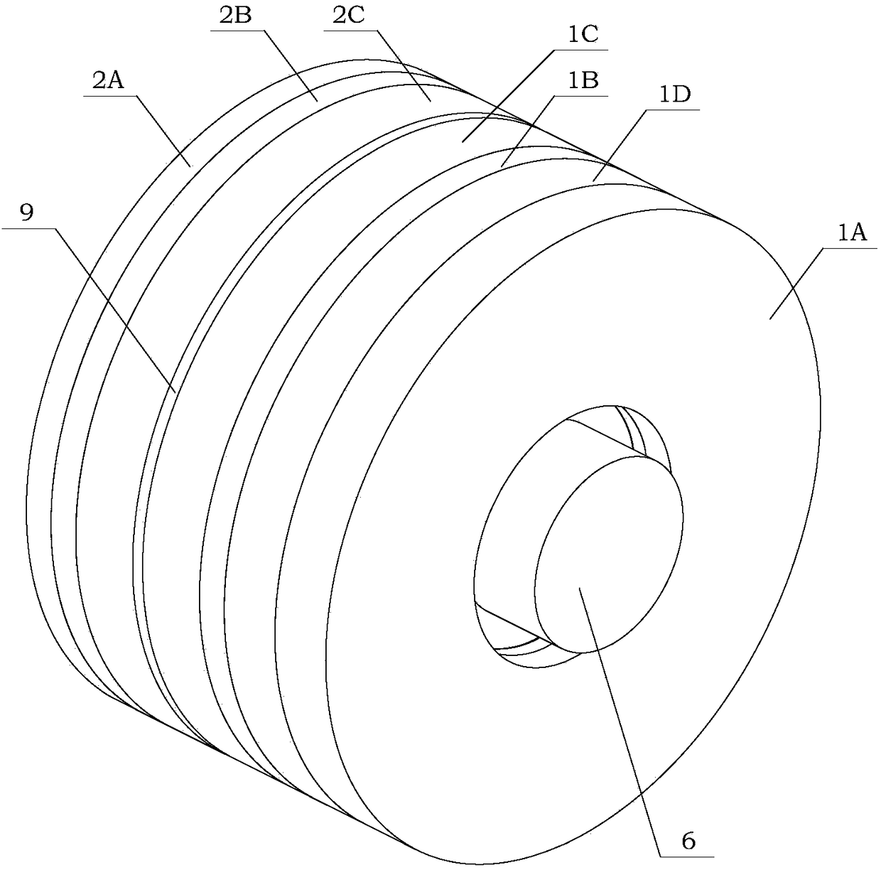
[0153] See Picture 9 As shown, the orthogonal magnetic path axis integrated magnetic suspension bearing based on the symmetrical self-lubricating flexible auxiliary bearing structure designed in the present invention is applied to a high-speed magnetic suspension motor for performance description.

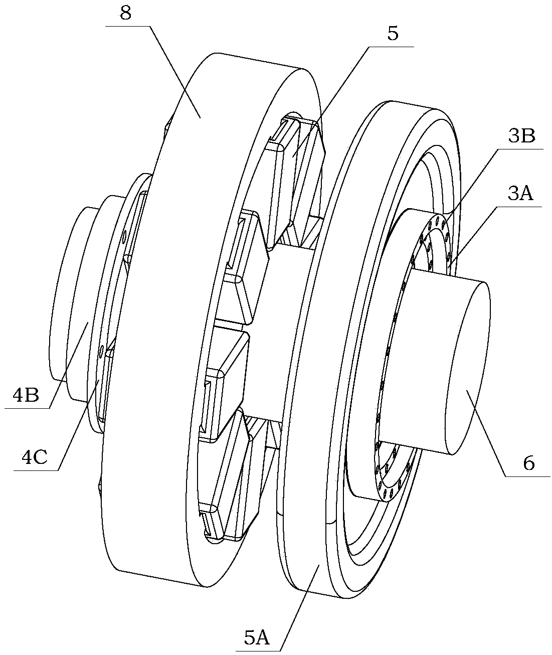
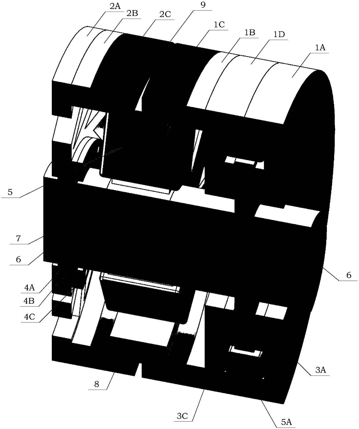
[0154] The orthogonal magnetic path shaft integrated magnetic bearing based on the symmetrical self-lubricating flexible auxiliary bearing structure designed in the present invention is applied to a high-speed magnetic levitation motor, that is, the rotor shaft 6 is replaced with the motor output shaft, and the assembled motor is assembled through the rotor core 7 Invented the orthogonal magnetic path axis integrated magnetic suspension bearing is installed on the output shaft of the motor, and a displacement sensor 20 is installed between the left side of the thrust plate 61 of the rotor shaft 6 and the stator core 8. The radial permeation flexible magnetic permeable ring 2A The stat...


PUM

PropertyMeasurementUnit
Wire diameteraaaaaaaaaa

Abstract

The invention discloses an orthogonal magnetic circuit radial-axial-integrated magnetic bearing based on a symmetrical self-lubricating flexible backup bearing structure. A radial magnetic bearing coil of the orthogonal magnetic circuit radial-axial-integrated magnetic bearing is mounted on a stator tooth set of a stator iron core; two radial rigid magnetic-conductive rings are mounted at an outerdisc of the stator iron core so as to prevent the short circuit problem of permanent magnetic circuits, wherein a certain gap exists between the two radial rigid magnetic-conductive rings; an axial magnetic bearing coil is located at a thrust disc of a rotor shaft and mounted in a cavity formed by the two magnetic-conductive rings; graphite rings and backup bearing skeletons which achieve the axial self-lubricating effect are arranged on the two sides of the thrust disc correspondingly; and a radial backup bearing skeleton and a graphite internal convex ring are arranged in an inner ring cavity of a radial flexible magnetic conductive ring for achieving the radial self-lubricating effect. By adopting the technical means that axial and radial electromagnetic circuits are combined into a whole, and a radial magnetic bearing and a backup bearing are combined into a whole, the technical problem that traditional magnetic bearings are low in coaxiality is solved.

Description

Technical field [0001] The invention relates to a magnetic suspension bearing, and more particularly, to an orthogonal magnetic path axis integrated magnetic suspension bearing based on a symmetrical self-lubricating flexible auxiliary bearing structure. Background technique [0002] Magnetic Bearing uses magnetic force to suspend the rotor in the air so that there is no mechanical contact between the rotor and the stator. [0003] For the structure of the magnetic levitation motor, please refer to "Modeling and Design of 3-DOF Magnetic Bearing for High-Speed ​​Motor Including Eddy-Current Effects and LeakageEffects", author Yue Yun, etc., Volume 63, Issue 6, June 2016, published in "IEEE TRANSACTIONS ONINDUSTRIAL ELECTRONICS". Of this document figure 1 The overall structure of a typical high-speed magnetic levitation motor is introduced. figure 1 In the right half of the high-speed magnetic suspension motor, the auxiliary bearing (Backup bearing) and the radial-axis integrated ma...

Claims


Application Information

Patent Timeline
IPC IPC(8): F16C32/04
CPCF16C32/044F16C32/0459F16C32/0474F16C32/0493F16C2380/26
Inventor 王坤李腾郑世强韩邦成
Owner BEIHANG UNIV
Why Eureka
Try Eureka