Automobile adjusting shock absorber and damping adjusting method thereof

A shock absorber and adjustment technology, which is applied in the field of automobile adjustment shock absorber damping adjustment and automobile adjustment shock absorber, can solve problems such as difficult operation, achieve cost saving, simple and convenient adjustment method, and easy operation Effect

Pending Publication Date: 2018-08-03
LIAONING UNIVERSITY OF TECHNOLOGY
View PDF10 Cites 1 Cited by
  • Summary
  • Abstract
  • Description
  • Claims
  • Application Information

AI Technical Summary

Problems solved by technology

[0002] In order to improve the ride comfort of the car, a shock absorber is installed in parallel with the elastic element in the suspension. In order to attenuate the vibration, the shock absorber used in the car suspension system is mostly a hydraulic shock absorber. When there is relative movement due to vibration, the piston in the shock absorber moves up and down, and the oil in the shock absorber cavity repeatedly flows from one cavity through different pores into another cavity. At this time, the gap between the hole wall and the oil Friction and the internal friction between oil molecules form a damping force on the vibration, so that the vibration energy of the car is converted into oil heat energy, which is then absorbed by the shock absorber and released into the atmosphere. One way to change the damping force is to adjust the size of the orifice. Damping, the other is to adjust the damping by changing the viscosity of the shock absorber fluid, but these two methods are not easy to operate

Method used


Image

  • Automobile adjusting shock absorber and damping adjusting method thereof
  • Automobile adjusting shock absorber and damping adjusting method thereof
  • Automobile adjusting shock absorber and damping adjusting method thereof

Examples


Embodiment Construction

[0058] The present invention will be further described in detail below in conjunction with the accompanying drawings, so that those skilled in the art can implement it with reference to the description.

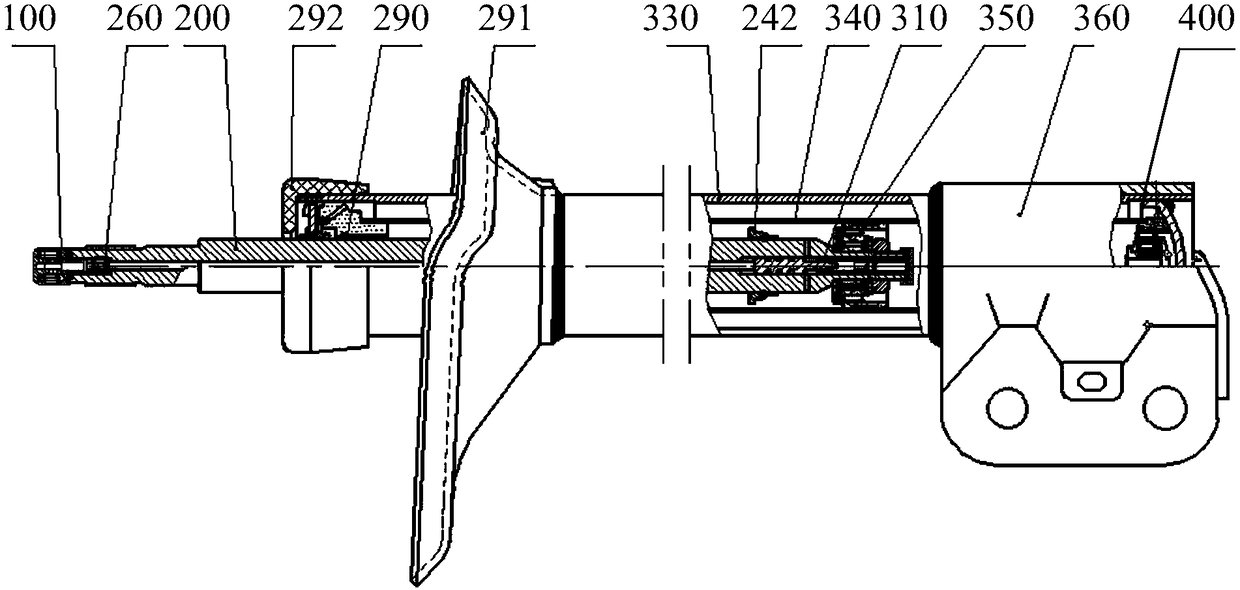
[0059] like figure 1 As shown, the automobile tuning shock absorber provided by the present invention includes: a damping tuning actuator 100 , a piston rod 200 and a valve train 300 .

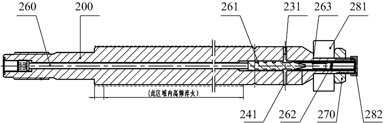
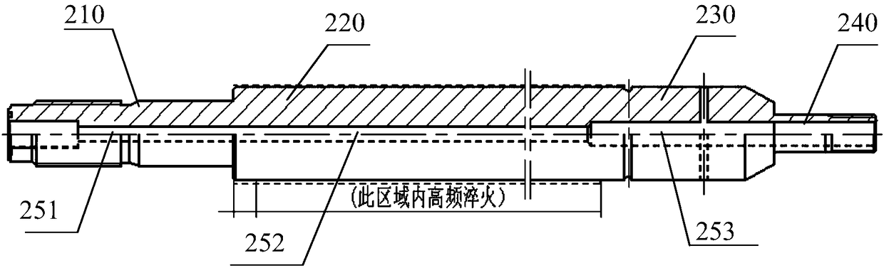
[0060] The piston rod 200 is hollow, and the hollow rod cavity is used for installing the adjusting rod 260 and the throttle valve assembly 310 . Both ends of the piston rod have a threaded structure, and the user end also has an internal threaded structure. There is a cross hole 231 on the piston rod 200, so that the oil generates a small hole high pressure during the recovery stroke of the piston rod. The shaft section with the largest shaft diameter of the piston rod has a section area that is subjected to high-frequency quenching treatment to enhance its mechanical properties.

[0061] ...


PUM


Abstract

The invention provides an automobile adjusting shock absorber which comprises a piston rod, an adjusting rod, a throttling pin, a through hole, a throttling seat and a one-way valve, wherein the piston rod is provided with a hollow cavity penetrating through the axial direction; the adjusting rod is arranged at the upper part of the interior of the hollow cavity and can move in the axial directionof the piston rod; the throttling pin is provided with a tapered front end and is arranged in the hollow cavity; the rear end of the throttling pin is propped against the lower end of the adjusting rod; the throttling pin can move in the axial direction of the piston rod; the through hole is formed in the side face, corresponding to the lower part of the throttling pin, of the lower part of the piston rod and communicates with the hollow cavity of the piston rod; the throttling seat is provided with a through hole in the axial direction; the tapered front end part of the throttling pin is fixed in the hollow cavity and stretches into the throttling seat; and the one-way valve is arranged in the throttling seat. Through changing the position of the adjusting rod in the axial direction of the piston rod, the automobile adjusting shock absorber changes the flow rate of oil between the cavities in the two sides of the piston rod to easily realize adjustment of damping force size. The invention further provides a damping adjusting method of the automobile adjusting shock absorber.

Description

technical field [0001] The invention relates to a device in the technical field of automobile shock absorbers, more precisely, the invention relates to an automobile adjustment shock absorber and a method for adjusting the damping of the automobile adjustment shock absorber. Background technique [0002] In order to improve the ride comfort of the car, a shock absorber is installed in parallel with the elastic element in the suspension. In order to attenuate the vibration, the shock absorber used in the car suspension system is mostly a hydraulic shock absorber. When there is relative movement due to vibration, the piston in the shock absorber moves up and down, and the oil in the shock absorber cavity repeatedly flows from one cavity through different pores into another cavity. At this time, the gap between the hole wall and the oil Friction and the internal friction between oil molecules form a damping force on the vibration, so that the vibration energy of the car is conv...

Claims


Application Information

Patent Timeline
Patent Type & Authority Applications(China)
IPC IPC(8): F16F9/44F16F9/18F16F9/34
CPCF16F9/182F16F9/185F16F9/187F16F9/34F16F9/44F16F2230/186
Inventor 孙晓帮薛少科苏春阳衣明悦财琴王一臣任延利
Owner LIAONING UNIVERSITY OF TECHNOLOGY
Why Eureka
Try Eureka