Anti-dry-burning electric heating faucet valve element and faucet made of same

An electric hot water faucet and anti-dry-burning technology, applied in the field of faucets, can solve the problems of accelerated aging of the water tank, damage to the electric heating tube, reduction of the service life of the faucet, etc., and achieve the effect of preventing dry-burning

Pending Publication Date: 2018-08-03
ZHEJIANG CHIXIN IND CO LTD
View PDF0 Cites 2 Cited by
  • Summary
  • Abstract
  • Description
  • Claims
  • Application Information

AI Technical Summary

Problems solved by technology

In the case of hot water, when the switch valve is opened, because the water tank will not be filled with water at once, and the tap water contains a lot of gas, it will cause dry burning and damage the electric heating tube; When the water level switch valve is closed, the water flow stops, and the electric heating tube will continue to heat the water in the water tank of the faucet. Since the water tank of the electric water faucet is basically made of plastic material, the aging of the plastic water tank will be accelerated over time, reducing the service life of the faucet; Water enters, but the water tank is still heated, which will cause the risk of the next person using hot water, that is, high-temperature water suddenly comes out of the water tank and scalds people

Method used


Image

  • Anti-dry-burning electric heating faucet valve element and faucet made of same
  • Anti-dry-burning electric heating faucet valve element and faucet made of same
  • Anti-dry-burning electric heating faucet valve element and faucet made of same

Examples


Embodiment Construction

[0020] The present invention will be further described and explained below in conjunction with accompanying drawing.

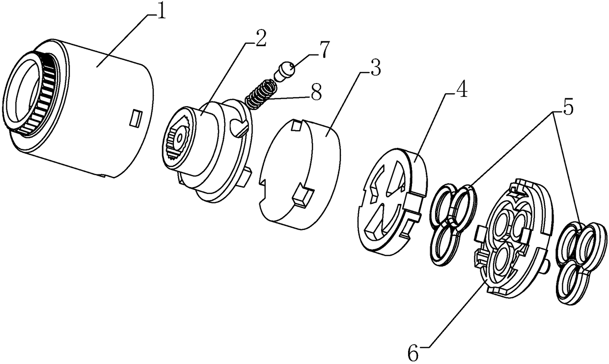
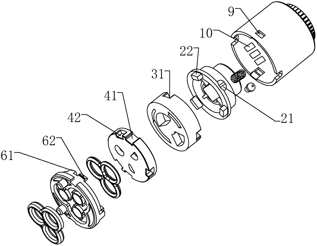
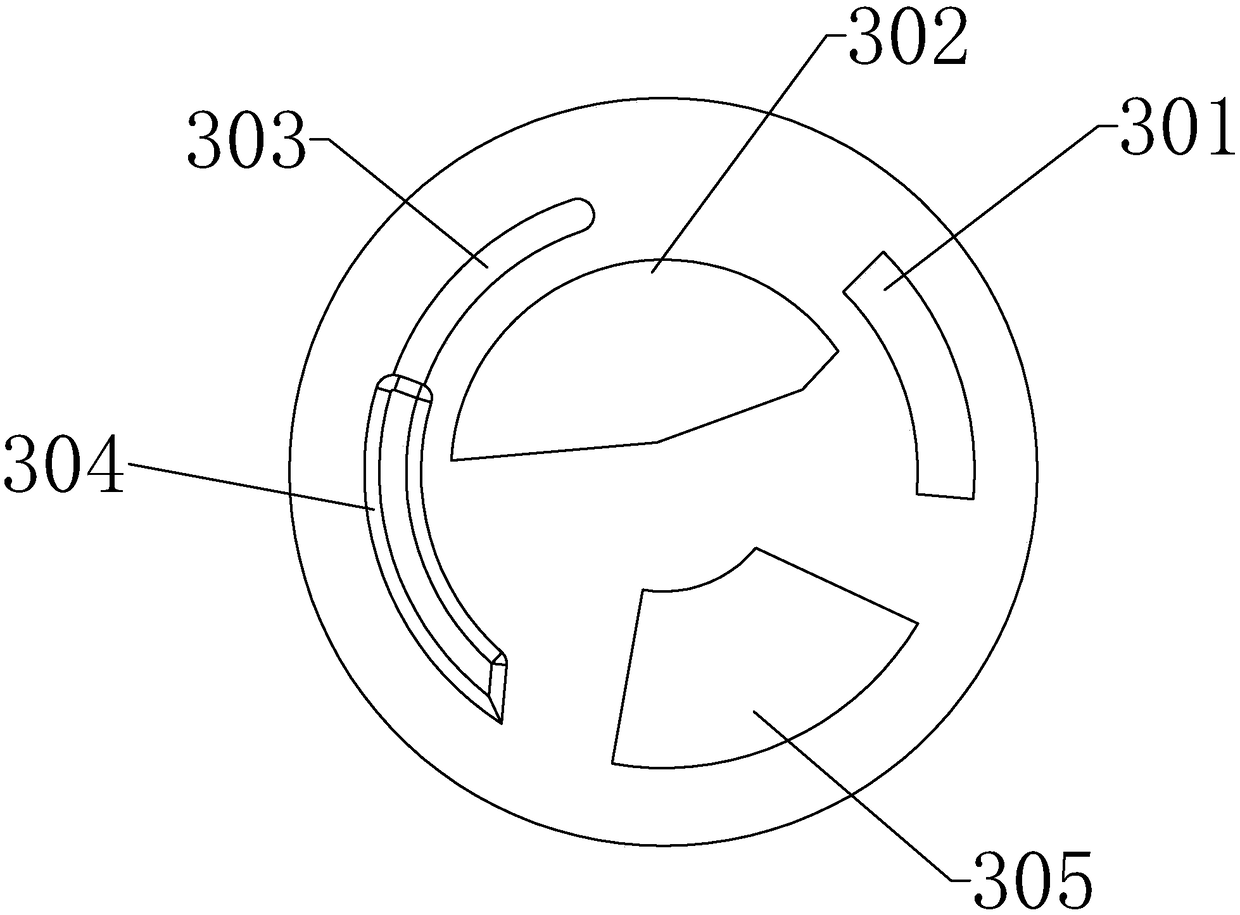
[0021] Such as Figure 1-4 As shown, a valve core of an anti-dry electric hot water faucet comprises a valve core assembly 12 composed of a rotationally fitted housing 1 and a rotor 2, upper and lower ceramic sheets for controlling hot and cold water discharge, and a flat base 6 equipped with a silicone sealing ring 5. , the side of the upper ceramic sheet 3 corresponding to the lower ceramic sheet 4 is provided with a cold water flow control groove 302, a pressure inlet groove 305, a pressure relief groove 301 and a hot water flow control groove, and the upper ceramic sheet 3 and the rotor 2 are buckled and matched The cold water flow control groove 302 and the pressure inlet groove 305 are fan-shaped and relatively arranged; the hot water flow control groove is a groove-like structure, and is arranged on the cold water flow control groove 302 and the pressur...


PUM


Abstract

The invention discloses an anti-dry-burning electric heating faucet valve element and a faucet made of the same and relates to electric heating faucets and components thereof. An upper ceramic wafer of the valve element is matched with a rotor in a buckled manner; a lower ceramic wafer is fixedly buckled to a flat foot base, and the flat foot base is fixedly buckled to an outer shell; and a cold water flow control groove, a pressure input groove, a pressure relief groove and a hot water flow control groove which are formed in the upper ceramic wafer are matched with a water inlet slotted hole,a water tank communicating slotted hole and an adhesive film cavity slotted hole which are formed in the lower ceramic wafer in a rotary manner, so that cold water and hot water are controlled. The anti-dry-burning electric heating faucet valve element is applicable to all the current electric heating faucets which are under water pressure control. A switching valve is connected with the rotor ina rotary manner and can only be switched on in one direction. The faucet outputs the cold water in the first place and then slowly conducts heating to output the hot water, and the scald risk is avoided; and therefore, when heating is conducted through electric heating tubes, the water tank is filled with water all the time, and the dry-burning phenomenon is avoided. The pressure relief groove isadopted to effectively cut off a switch in the adhesive film cavity slotted hole, and in other words, work of the electric heating tubes is cut off; and furthermore, the dry-burning phenomenon is stopped.

Description

technical field [0001] The invention relates to an electric water faucet and parts thereof, in particular to a valve core of an anti-dry electric water faucet and a water faucet made of the valve core. Background technique [0002] Generally, electric faucets are based on the closed state of the on-off valve, turning out cold water on one side, and hot water on the other side. In the case of hot water, when the switch valve is opened, because the water tank will not be filled with water at once, and the tap water contains a lot of gas, it will cause dry burning and damage the electric heating tube; When the water switch valve is closed, the water flow stops, and the electric heating tube will continue to heat the water in the water tank of the faucet. Since the water tank of the electric water faucet is basically made of plastic material, the aging of the plastic water tank will accelerate over time, reducing the service life of the faucet; Water enters, but the water tank ...

Claims


Application Information

Patent Timeline
Patent Type & Authority Applications(China)
IPC IPC(8): F16K3/08F16K3/30
CPCF16K3/08F16K3/30
Inventor 朱将来翁潥潥张吕周
Owner ZHEJIANG CHIXIN IND CO LTD
Why Eureka
Try Eureka