Thermal barrier tester of infrared imaging device

A technology of infrared imaging and test equipment, which is applied in the direction of image communication, laboratory equipment, housing or chamber, etc., can solve the problems of operator burns, failure to obtain test data, uncontrollable temperature of optical dome, etc., to achieve constant temperature, The effect of safe operation and accurate test data

Active Publication Date: 2014-06-11
THE GENERAL DESIGNING INST OF HUBEI SPACE TECH ACAD
View PDF4 Cites 0 Cited by
  • Summary
  • Abstract
  • Description
  • Claims
  • Application Information

AI Technical Summary

Problems solved by technology

Since the temperature of the heated optical dome is as high as 100°C, there is a potential safety hazard of scalding the operator during operation
In addition, during the process of taking the optical dome out of the high-temperature box and placing it in front of the infrared imager, the temperature of the optical dome will change, that is, the temperature of the optical dome cannot be controlled during the test process, and accurate test data cannot be obtained
Therefore, the above two test methods are unable to meet the needs of infrared imager thermal barrier test

Method used


Image

  • Thermal barrier tester of infrared imaging device
  • Thermal barrier tester of infrared imaging device
  • Thermal barrier tester of infrared imaging device

Examples


Embodiment Construction

[0012] The present invention will be further described in detail below in conjunction with the accompanying drawings and specific embodiments.

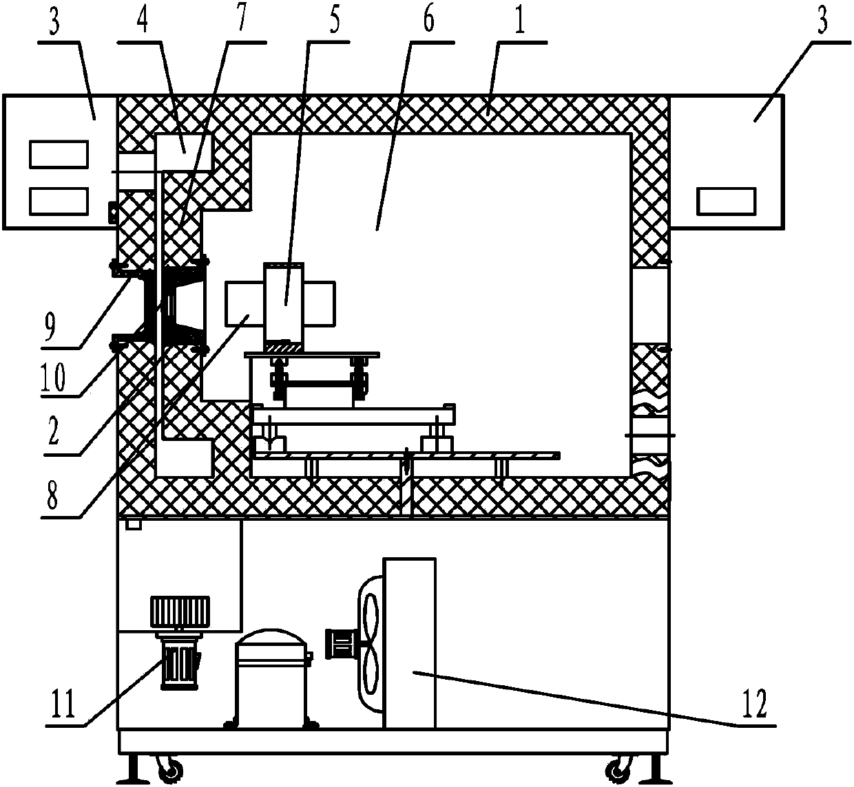
[0013] Such as figure 1 As shown, the infrared imager thermal barrier test device of the present invention includes a thermostat 1, the inner cavity of the thermostat 1 is provided with a heat insulating layer 7, and the thermostat 7 isolates the thermostat 1 into a low temperature zone 6 and a high temperature zone 4, and the low temperature zone Zone 6 and high temperature zone 4 are respectively provided with temperature controllers 3 . In order to ensure that the heating rate of the high temperature zone 4 meets the requirements, the space of the high temperature zone 4 can be reduced as much as possible. Specifically, the height of the high temperature zone 4 and the low temperature zone 6 are both 900mm in depth, the high temperature zone 4 has a width of 150mm, the temperature range is 10-300°C, and the heating rate is not les...


PUM


Abstract

The invention discloses a thermal barrier tester of an infrared imaging device, which comprises an incubator, wherein an inner cavity of the incubator is provided with a thermal insulation layer; the thermal insulation layer divides the incubator into a low-temperature region and a high-temperature region; the wall surface of the thermal insulation layer is provided with a fairing fixture, and is used for fixing an optical fairing in the infrared imaging device; an inner cavity of the low-temperature region is internally provided with a mounting rack of the infrared imaging device, and is used for fixing components except for the optical fairing in the infrared imaging device; and the incubator wall of the incubator at the side of the high-temperature region is provided with an observation window which is corresponding to the part of the fairing fixture and acts as a cameral shooting channel of the infrared imaging device. The thermal barrier tester of the infrared imaging device simulates different temperatures of the outer surface of the optical fairing and a cabin of the infrared imaging device by utilizing the high-temperature region and the low-temperature region of the incubator so as to verify the attenuation characteristic of the imaging quality of the infrared imaging device under the thermal barrier condition, the temperature of the optical fairing in the verifying process can be ensured to be constant, the test data is accurate, also the scalding hazard does not exist, and the operation is safe.

Description

technical field [0001] The invention relates to infrared imager test equipment, in particular to an infrared imager thermal barrier test device. Background technique [0002] During the high-speed flight of the infrared imager, due to the influence of the aerodynamic heating of the atmosphere, the optical dome itself will generate infrared radiation, and the thermal clutter of the optical dome will enter the field of view and cause attenuation of the imaging quality, reducing the signal-to-noise ratio of the imaging system , so that the imaging is blurred, and even forms a thermal barrier effect and cannot be imaged in severe cases. [0003] In order to verify the attenuation characteristics of the thermal barrier effect on the imaging quality of the infrared imager, there are two verification methods usually used: one is to use wind tunnel test, and the other is to use single temperature box heating. The wind tunnel test method is generally to use the arc wind tunnel to si...

Claims


Application Information

Patent Timeline
Patent Type & Authority Patents(China)
IPC IPC(8): B01L1/00H04N17/00
Inventor 史要涛武春风庹文波吴丰阳柯才军
Owner THE GENERAL DESIGNING INST OF HUBEI SPACE TECH ACAD
Why Eureka
Try Eureka