Capillary force vaporizer device instantly generating vapor

A technology of capillary force and vaporizer, which is applied in the direction of steam generating device, steam generation, space heating and ventilation details, etc., can solve the problems of high energy consumption, low safety factor, large volume and difficulty, and achieve high safety factor and fast response time Short, less safe effect

Inactive Publication Date: 2019-05-28
CHINA UNIV OF PETROLEUM (EAST CHINA)
View PDF8 Cites 0 Cited by
  • Summary
  • Abstract
  • Description
  • Claims
  • Application Information

AI Technical Summary

Problems solved by technology

According to the survey, among many meteorological environment elements, air humidity has the greatest impact on respiratory diseases. The research results and clinical practice have proved that only when the air humidity in the room reaches 55% to 65%, it is more conducive to the prevention and treatment of various lower respiratory diseases. For treatment and rehabilitation, low humidity often leads to aggravation of the condition, and an environment with high relative humidity is suitable for the growth and reproduction of bacteria and other microorganisms. In order to alleviate and solve respiratory diseases, the current market mainly includes direct evaporation humidifiers and compressors. There are two types of nebulizers, but besides high energy consumption, easy fouling, and low safety factor, the biggest disadvantage of humidifiers is that they provide a warm and humid environment indoors, which is easy for bacteria, mold and other microorganisms to breed. Compressed nebulizers The disadvantage is that it is bulky and not easy to carry, and it is noisy. The tap water used in the above products contains magnesium, calcium and other mineral ions that will be sprayed into the air with the atomized water droplets and enter the body with our breath. If long-term excessive inhalation is harmful to health, it is easy to cause allergies and various respiratory diseases

Method used


Image

  • Capillary force vaporizer device instantly generating vapor
  • Capillary force vaporizer device instantly generating vapor
  • Capillary force vaporizer device instantly generating vapor

Examples


Embodiment Construction

[0027] The following will clearly and completely describe the technical solutions in the embodiments of the present invention with reference to the accompanying drawings in the embodiments of the present invention. Obviously, the described embodiments are only some, not all, embodiments of the present invention. Based on the embodiments of the present invention, all other embodiments obtained by persons of ordinary skill in the art without making creative efforts belong to the protection scope of the present invention.

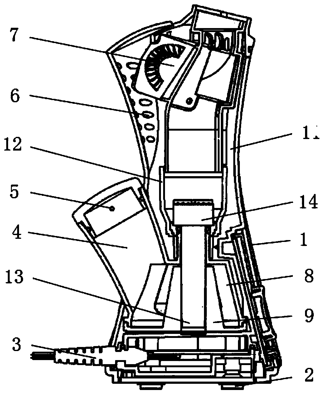
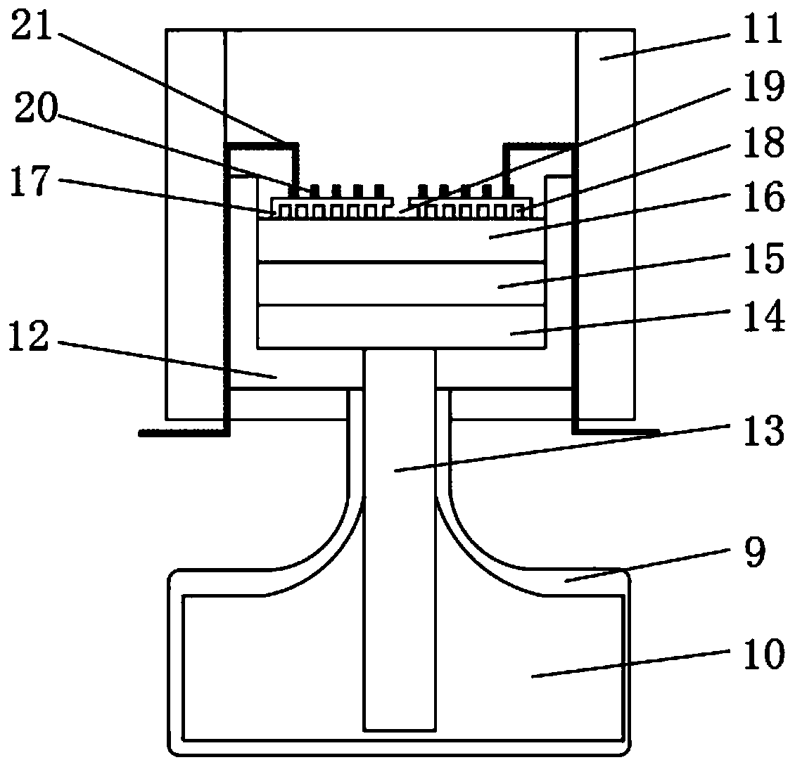
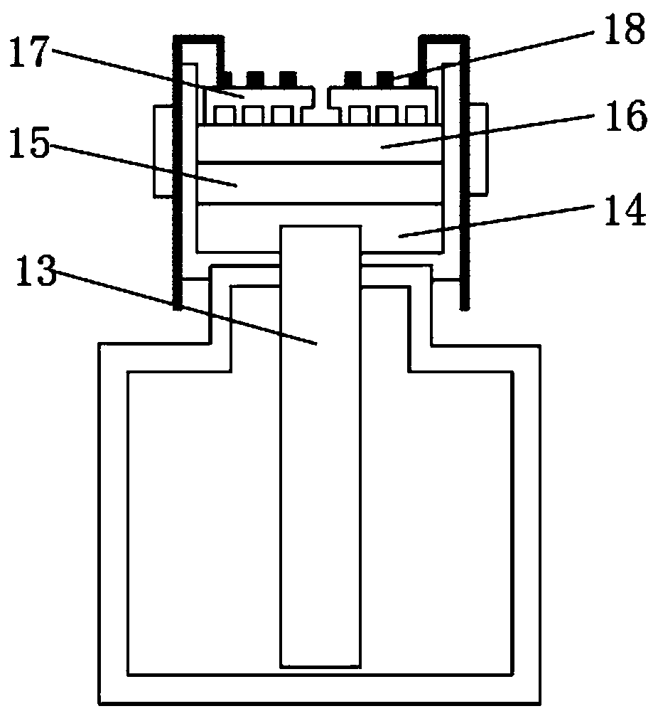
[0028] see Figure 1-6 , the present invention provides a technical solution: a capillary force vaporizer device for generating steam instantaneously, including a device main body 1, and legs 2 are fixedly installed at the corners of the lower outer surface of the device main body 1, and one side of the device main body 1 A power cord 3 is movably installed at the lower end of the surface, a water supply pipe 4 is fixedly installed in the middle of one side of...


PUM


Abstract

The invention discloses a capillary force vaporizer device instantly generating vapor. The capillary force vaporizer device comprises a device body. Supporting feet are fixedly installed in the cornerpositions of the outer surface at the lower end of the device body, a power line is movably installed at the lower end of the outer surface on one side of the device body, a water adding pipe is fixedly installed in the middle position of the outer surface on one side of the device body, and vapor outflow holes are formed in the position, near the upper end, of the outer surface of the device body. By the adoption of the capillary force vaporizer device instantly generating the vapor, after being sucked through capillary force, liquid is scattered to become small-size liquid in the capillarytube diameter size and heated so as to instant evaporate, air streams are sprayed out continuously and stably, the capillary force vaporizer device can operate without movable parts such as an air pump, meanwhile, the control ability of the gas ejection amount is quite high, due to the fact that the liquid is directly changed into water vapor to enter the oral cavity and the nasal cavity of a person, the problem that a warm and humid environment is provided for microorganisms such as bacteria does not exist, and a safety coefficient is high.

Description

technical field [0001] The invention relates to the field of vaporizer devices, in particular to a capillary force vaporizer device for instantaneously generating steam. Background technique [0002] In recent years, due to the aggravation of air pollution and climate change, the incidence of respiratory diseases such as pharyngitis is increasing. According to the survey, among many meteorological environment elements, air humidity has the greatest impact on respiratory diseases. The research results and clinical practice have proved that only when the air humidity in the room reaches 55% to 65%, it is more conducive to the prevention and treatment of various lower respiratory diseases. For treatment and rehabilitation, low humidity often leads to aggravation of the condition, and an environment with high relative humidity is suitable for the growth and reproduction of bacteria and other microorganisms. In order to alleviate and solve respiratory diseases, the current market...

Claims


Application Information

Patent Timeline
Patent Type & Authority Applications(China)
IPC IPC(8): F24F6/10F24F13/00F22B33/18
Inventor 曾兰李哲王晓伟闫嘉琦赵宇程
Owner CHINA UNIV OF PETROLEUM (EAST CHINA)
Why Eureka
Try Eureka