
Attack time and attach angle constrained guidance strategy

An angle and strategy technology, applied in the field of guidance strategy with attack time and attack angle constraints, can solve the problems of less research, conservative guidance methods, static target attack time and attack angle cannot be effectively applied to intercept moving targets, etc. The effect of strong applicability and simple design method

Active Publication Date: 2018-08-03
BEIHANG UNIV
View PDF6 Cites 27 Cited by
  • Summary
  • Abstract
  • Description
  • Claims
  • Application Information

AI Technical Summary

Problems solved by technology

However, there are relatively few researches on guidance methods with both attack time and attack angle constraints, especially for the design of attack time and angle-constrained guidance methods for moving targets
This is mainly due to the fact that target movement brings a series of uncertainties to the guidance system and guidance information, so that the attack time and attack angle constraint guidance law for stationary targets cannot be effectively applied to the situation of intercepting moving targets
At the same time, most of the existing attack time and angle-constrained guidance methods need to rely on the remaining time estimation information, or need to linearize the mathematical models of the missile and the target, or need to transform the kinematics and dynamics models into relative Because of the mathematical model of the horizontal range, this has caused a certain degree of conservatism to the designed guidance method, and also reduced the applicability of the guidance system

Method used


Image

  • Attack time and attach angle constrained guidance strategy
  • Attack time and attach angle constrained guidance strategy
  • Attack time and attach angle constrained guidance strategy

Examples


Embodiment Construction

[0062] The following will clearly and completely describe the technical solutions in the embodiments of the present invention with reference to the accompanying drawings in the embodiments of the present invention. Obviously, the described embodiments are only some, not all, embodiments of the present invention. All other embodiments obtained by persons of ordinary skill in the art based on the embodiments of the present invention belong to the protection scope of the present invention.

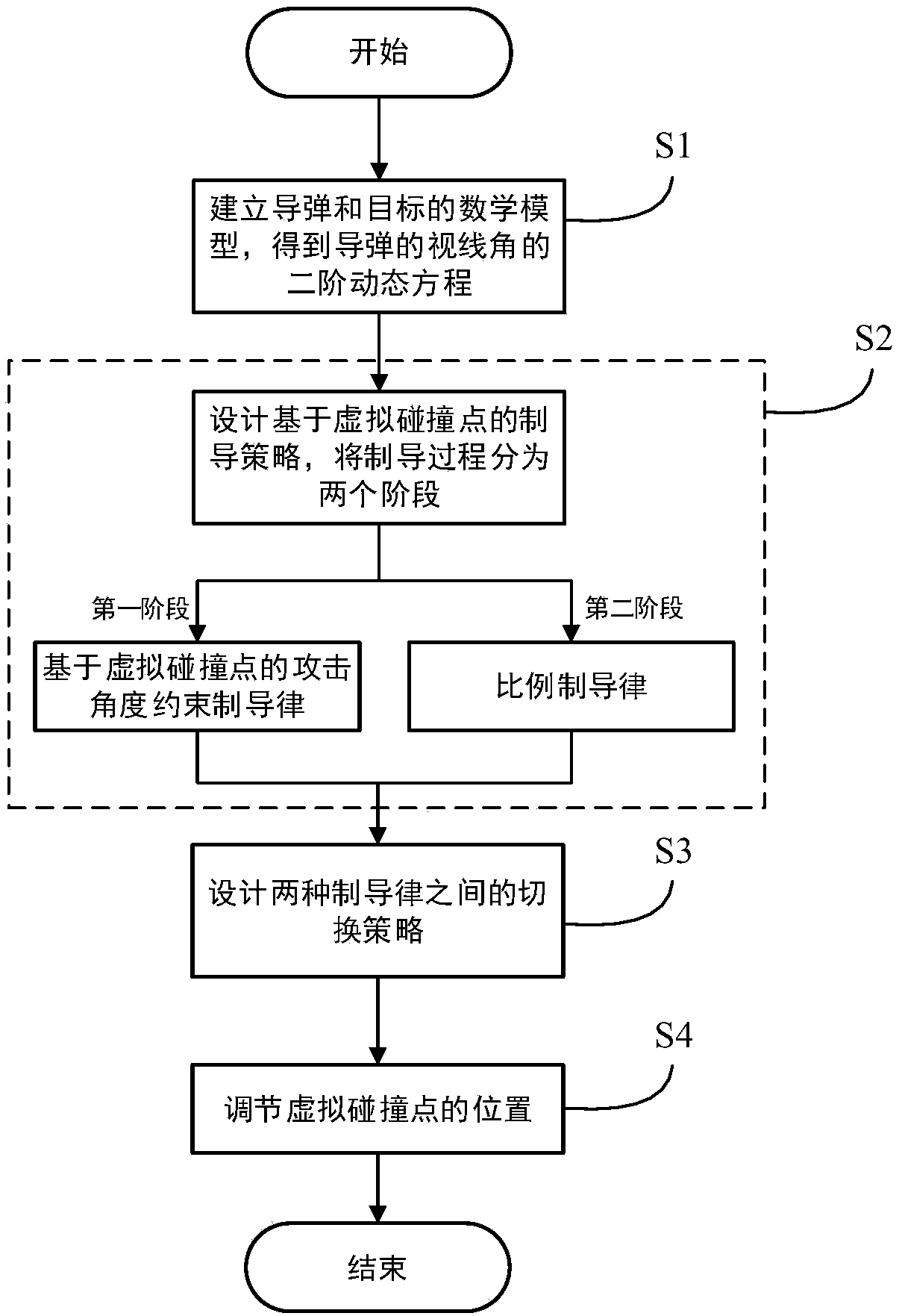
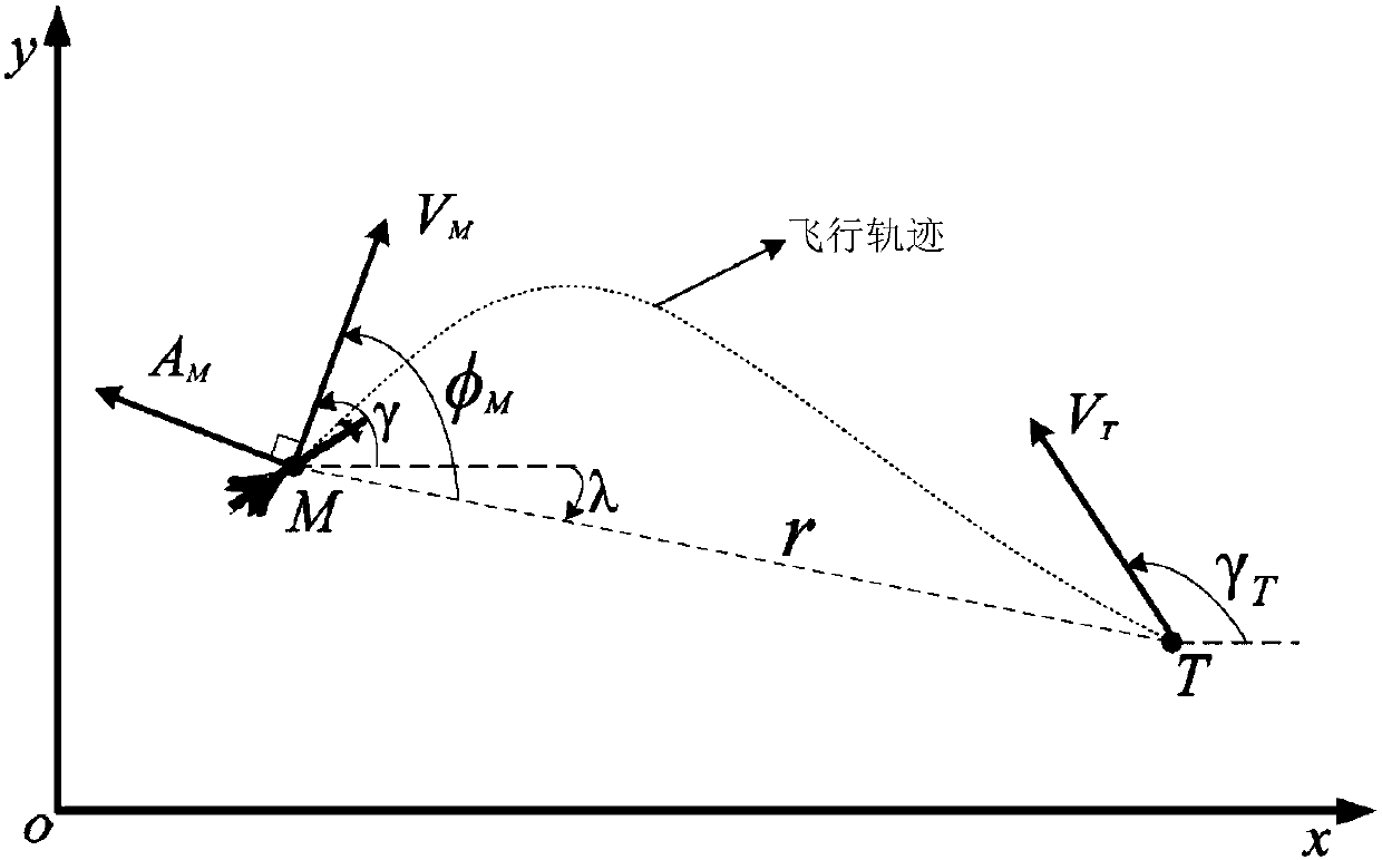
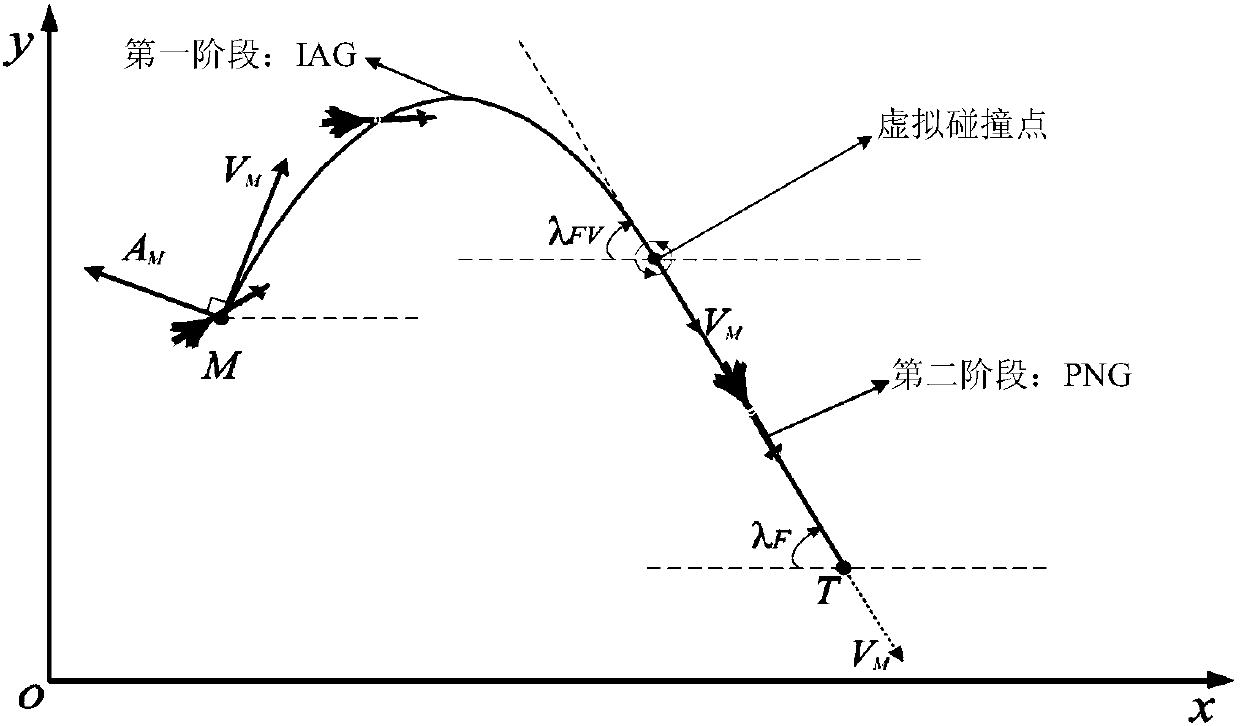
[0063] Such as figure 1 As shown, the steps of a guidance strategy with attack time and attack angle constraints of the present invention are as follows: first, based on the two-dimensional geometric relationship between the missile and the target, the relative kinematics and dynamics mathematical model of the missile and the target are established, and the missile The second-order dynamic equation of the line-of-sight angle; then, a guidance strategy based on the virtual collision point is d...


PUM


Abstract

The invention discloses an attack time and attach angle constrained guidance strategy. The attack time and attach angle constrained guidance strategy comprises the following steps of using a two-dimensional horizontal plane where a missile and a target are located as an attack plane, establishing a missile and target mathematical model and acquiring a missile sight angle second-order dynamic equation; designing the guidance strategy based on a virtual collision point, dividing the guidance process into two stages, designing an attack angle constrained guidance law based on the virtual collision point for the first stage and designing a proportional guidance law for the second stage; designing a switching strategy of the attack angle constrained guidance law and the proportional guidance law based on the virtual collision point; and adjusting the location of the virtual collision point. By means of the guidance strategy based on the virtual collision point, there is no need to conduct linearization and differential equation conversion based on the cross-range on the model and depend on estimation on remaining time information; the attack time and attach angle constrained guidance strategy is applicable to target moving tasks under multiple constraint conditions and has the characteristics that the design method is simple, and the applicability is high.

Description

technical field [0001] The invention belongs to the field of missile guidance system design, and in particular relates to a guidance strategy with attack time and attack angle constraints. Background technique [0002] At present, with the development trend of large-scale weapons and equipment more and more widely adopting close-in defense systems, the risk of completing a single missile attack mission based on traditional guidance laws has increased significantly, because a single missile can easily fly through traditional attack ballistics. Intercepted / destroyed by the opponent's defense system. In response to this problem, an effective attack strategy is to carry out a saturation attack on the target with multiple missiles to restrict the defense system with limited coverage. When this saturation attack strategy is also combined with the attack angle constraints, the survivability of the missile and the killing effect on the target will be greatly improved. The most cri...

Claims


Application Information

Patent Timeline
Patent Type & Authority Applications(China)
IPC IPC(8): F41G3/00
CPCF41G3/00
Inventor 胡庆雷韩拓郭雷王陈亮
Owner BEIHANG UNIV
Learn More