
Metal pipeline detecting system and method based on time-domain electromagnetic method

A time-domain electromagnetic and detection system technology, applied in the field of engineering geophysical prospecting, can solve the problems of inaccurate depth determination, weak anti-interference ability, and low detection accuracy, and achieve enhanced flexibility and applicability, strong effective signal response, and automatic detection. The effect of adaptation

Pending Publication Date: 2018-08-03
安徽晟北辰地质勘测设计有限公司
View PDF3 Cites 4 Cited by
  • Summary
  • Abstract
  • Description
  • Claims
  • Application Information

AI Technical Summary

Problems solved by technology

[0004] The technical problem to be solved by the present invention is: the frequency domain electromagnetic method has a shallow detection depth, it is difficult to effectively detect deep-buried metal pipelines, the anti-interference ability is weak, and the measurement signal is affected by surrounding electromagnetic interference, especially power frequency interference; Non-contact field source excitation is used in the detection of the method, which often causes early signal distortion and cannot be used. When this method is used to detect underground metal pipelines, it is easily affected by side metal interference and surrounding human electromagnetic interference. At the same time, the detection accuracy is low, especially inaccurate. Depth determination is more prominent for deeply buried pipelines, and it is difficult to continuously track the target pipeline to be measured

Method used


Image

  • Metal pipeline detecting system and method based on time-domain electromagnetic method
  • Metal pipeline detecting system and method based on time-domain electromagnetic method
  • Metal pipeline detecting system and method based on time-domain electromagnetic method

Examples


Embodiment Construction

[0046] In order to facilitate those skilled in the art to understand the technical solution of the present invention, the technical solution of the present invention will be further described in conjunction with the accompanying drawings.

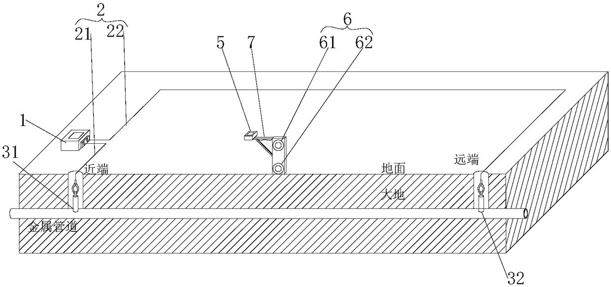
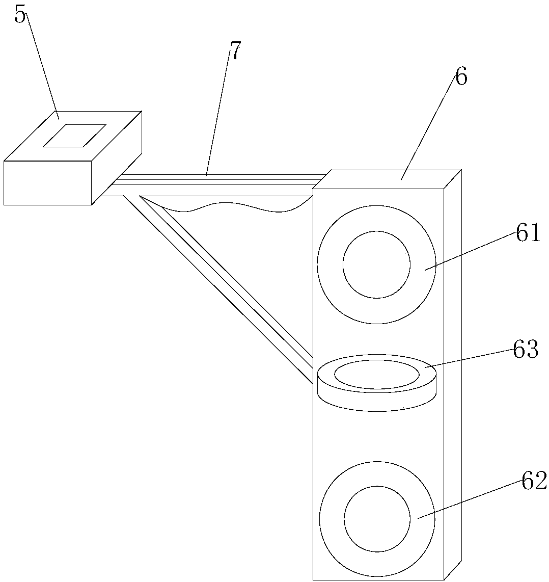
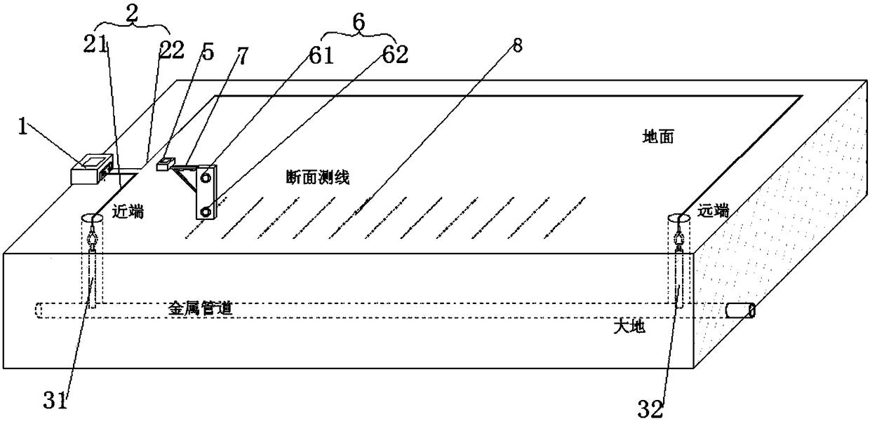
[0047] refer to figure 1 , the embodiment of the present invention provides a metal pipeline detection system based on time-domain electromagnetic method, the detection system has two connection points, namely the proximal connection point 31 and the far-end connection point 32; the detection system includes a transmitter 1, The sending connecting line 2, the measuring machine 5 and the receiving device 6, the sending machine 1 is respectively connected to two connecting points through the sending connecting line 2, wherein the near-end connecting point 31 is located at a dew point of the target pipeline close to the sending machine 1, and the far-end The end connection point 32 is located at the vertex adjacent to the near-end connection p...


PUM


Abstract

The invention discloses a metal pipeline detecting system based on a time-domain electromagnetic method. The metal pipeline detecting system has a proximal connecting point, a distal connecting point,a transmitter, a transmitting connecting line, a measuring machine and a receiving device. The system has a rectangular detecting area of which the short side is perpendicular to the approximate direction of a target pipeline, and of which the long side is parallel to the approximate direction of the target pipeline. The proximal connecting point is located at an exposed point of the target pipeline and corresponds to a vertex of the rectangular detecting area. The distal connecting point is located at a vertex of the rectangular detecting area adjacent to the proximal connecting point. The transmitting connecting line is disposed on the side of the detecting area. The receiving device is connected to the measuring machine through a mounting frame. The measuring machine and the transmitter are timed and set parameters before detection. The system has the advantages that the to-be-detected section of the target pipeline is directly put in the transmission loop in order to guarantee that an excitation field source is applied to the target pipeline to the utmost extent, a response signal is stronger and the side electromagnetic interference can be reduced, and the to-be-detected pipeline can be precisely positioned, orientated and continuously tracked.

Description

technical field [0001] The invention belongs to the technical field of engineering geophysical prospecting, and in particular relates to a metal pipeline detection system and method based on a time-domain electromagnetic method. Background technique [0002] Underground pipelines are important infrastructure and "lifelines" of cities. The development, construction and management of cities have increasingly prominent demand for detection of underground pipelines; there are many types of urban underground pipelines, with a large number, various materials, and different laying techniques. They often have to pass through ground structures. Roads, railways, rivers, etc., the landform, topography, and soil quality that pass through are complex and changeable. Especially for deep-buried pipelines, trenchless laying technology is often used, and the buried depth and variation range are large. Usually, the buried depth of the pipe top is greater than 3 meters. , the local buried dept...

Claims


Application Information

Patent Timeline
IPC IPC(8): G01V3/08G01V3/10
CPCG01V3/08G01V3/104
Inventor 倪子涵计成富陈陆望孙尚云赵萍曹爽余睿泽张闪闪翟福勤
Owner 安徽晟北辰地质勘测设计有限公司
Learn More