
Power distribution cabinet convenient to move

A technology for power distribution cabinets and cabinet doors, which is applied in substation/power distribution device casings, electrical components, substation/switch layout details, etc., and can solve problems such as low reliability, looseness, and easy vibration damage of electrical components. To achieve the effect of reliable and practical structure, preventing vibration damage and stable placement

Inactive Publication Date: 2018-08-03
CHENGDU JUNSHUO RUIZHI INFORMATION TECH CO LTD
View PDF0 Cites 2 Cited by
  • Summary
  • Abstract
  • Description
  • Claims
  • Application Information

AI Technical Summary

Problems solved by technology

[0003] At present, in order to facilitate the movement of the power distribution cabinet, moving wheels are often installed at the bottom of the power distribution cabinet. Although the movable function is realized, the direct load of the moving wheel cannot ensure the stability of the power distribution cabinet, and the reliability is not high. Secondly, , the electrical components are generally directly fixed on the mounting board inside the power distribution cabinet. When subjected to a certain vibration, the electrical components are easy to vibrate, damage or loosen.

Method used


Image

  • Power distribution cabinet convenient to move
  • Power distribution cabinet convenient to move
  • Power distribution cabinet convenient to move

Examples


Embodiment Construction

[0019] The following will clearly and completely describe the technical solutions in the embodiments of the present invention with reference to the accompanying drawings in the embodiments of the present invention. Obviously, the described embodiments are only some, not all, embodiments of the present invention.

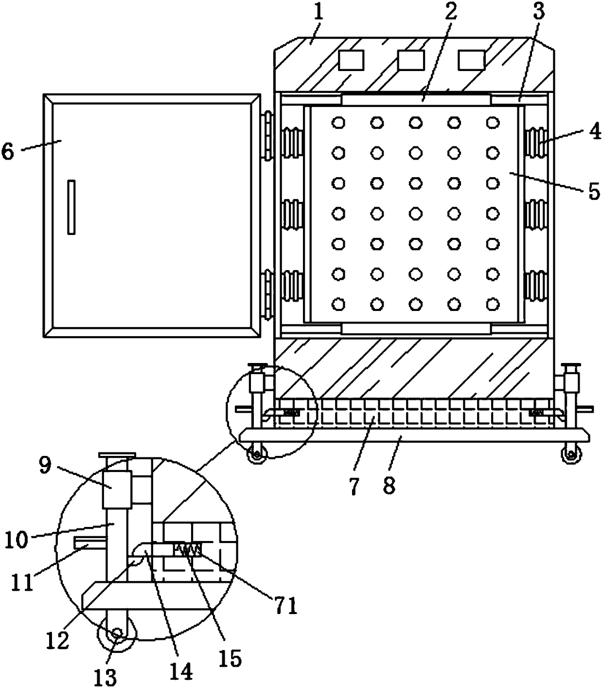
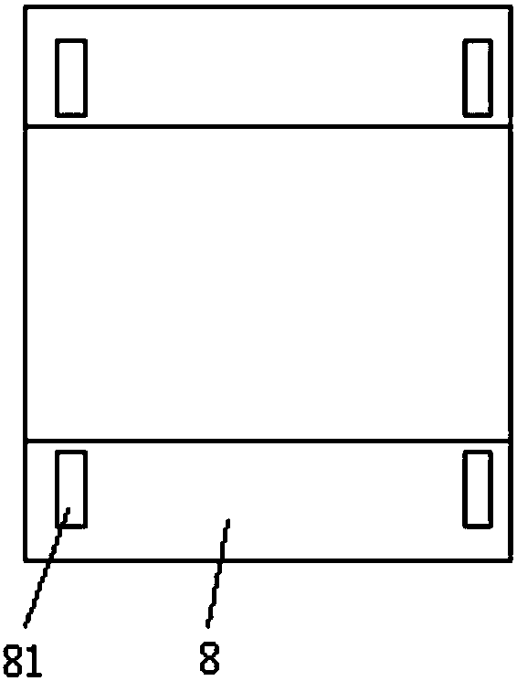
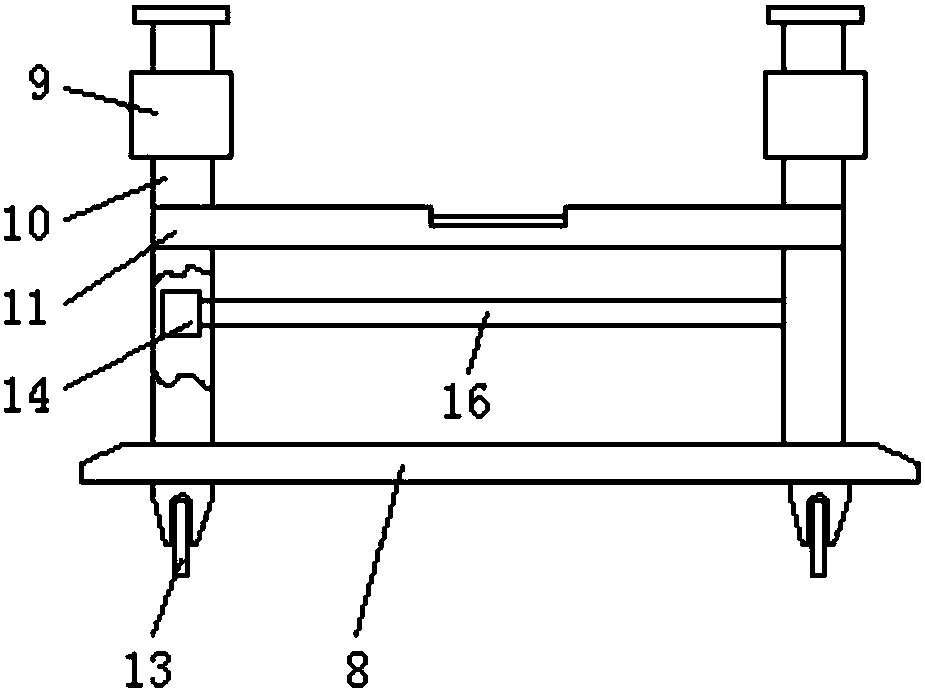
[0020] refer to Figure 1-3 , a power distribution cabinet that is easy to move, including a power distribution cabinet shell 1 and a cabinet door 6, and the cabinet door 6 is movably connected to the power distribution cabinet shell 1 through hinges, and the upper and lower sides of the power distribution cabinet shell 1 are parallel Two sliding rods 3 are provided, and the first sliding sleeve 2 is slidably sleeved on the two sliding rods 3, and a mounting plate 5 is welded between the two first sliding sleeves 2, and both sides of the mounting plate 5 pass through The shock-absorbing springs 4 arranged equidistantly along the vertical direction are elastically con...


PUM


Abstract

The invention discloses a power distribution cabinet convenient to move. The power distribution cabinet comprises a power distribution cabinet shell and a cabinet door, wherein the cabinet door is moveably connected with the power distribution cabinet shell through a hinge; two sliding rods are arranged in parallel on the upper side and the lower side inside the power distribution cabinet shell; the two sliding rods are sleeved by first sliding sleeves; a mounting plate is welded between the two first sliding sleeves. Due to adoption of the sliding rods and the first sliding sleeves, displacement of the mounting plate in a vertical direction can be inhibited, and structural stability can be ensured; due to adoption of a damping spring, transverse vibration energy can be absorbed, then electric elements on the mounting plate can be protected, and the electronic elements can be prevented from vibration damage; in addition, due to cooperation of a first limiting block and a second limiting block, switching of moving wheel bearing and base bearing can be easily completed, then free movement of the power distribution cabinet can be ensured, in addition, the power distribution cabinet can be stably placed, and the power distribution cabinet is reliable and practical in structure.

Description

technical field [0001] The invention relates to the technical field of electrical equipment, in particular to a mobile distribution cabinet. Background technique [0002] The power distribution cabinet (box) is divided into power distribution cabinet (box), lighting distribution cabinet (box), metering cabinet (box), and is the final equipment of the power distribution system. The cabinet is used in the occasions where the load is relatively scattered and there are few circuits; the motor control center is used in the occasions where the load is concentrated and there are many circuits. They distribute the electric energy of a certain circuit of the upper-level power distribution equipment to the nearby load. The load provides protection, monitoring and control. [0003] At present, in order to facilitate the movement of the power distribution cabinet, moving wheels are often installed at the bottom of the power distribution cabinet. Although the movable function is realize...

Claims


Application Information

Patent Timeline
Patent Type & Authority Applications(China)
IPC IPC(8): H02B1/30H02B1/38H02B1/52H02B1/54
Inventor 张德彬
Owner CHENGDU JUNSHUO RUIZHI INFORMATION TECH CO LTD
Learn More