A control method for reactive power compensation of distributed photovoltaic power plants

A distributed photovoltaic and power station technology, applied in reactive power compensation, photovoltaic power generation, reactive power adjustment/elimination/compensation, etc., can solve power factor does not meet the requirements, active power consumption becomes smaller, reactive power consumption, etc. problem, to achieve the effect of ensuring that the power factor meets the standard

Active Publication Date: 2019-12-24
THE IT ELECTRONICS ELEVENTH DESIGN & RES INST SCI & TECHNOLOGICAL ENG
View PDF5 Cites 0 Cited by
  • Summary
  • Abstract
  • Description
  • Claims
  • Application Information

AI Technical Summary

Problems solved by technology

[0004] The existing power factor calculation method is the root mean square of the total active power ratio of the sum of active power and reactive power within a certain period of time. However, in the actual operation of distributed photovoltaic power plants, various Under the circumstances, the accumulated reactive power consumption is very large, and the active power consumption of the load after reducing the photovoltaic output is getting smaller, and the power factor may not meet the requirements.

Method used


Image

  • A control method for reactive power compensation of distributed photovoltaic power plants
  • A control method for reactive power compensation of distributed photovoltaic power plants
  • A control method for reactive power compensation of distributed photovoltaic power plants

Examples


Embodiment Construction

[0034] In order to make the object, technical solution and advantages of the present invention clearer, the implementation manner of the present invention will be further described in detail below in conjunction with the accompanying drawings.

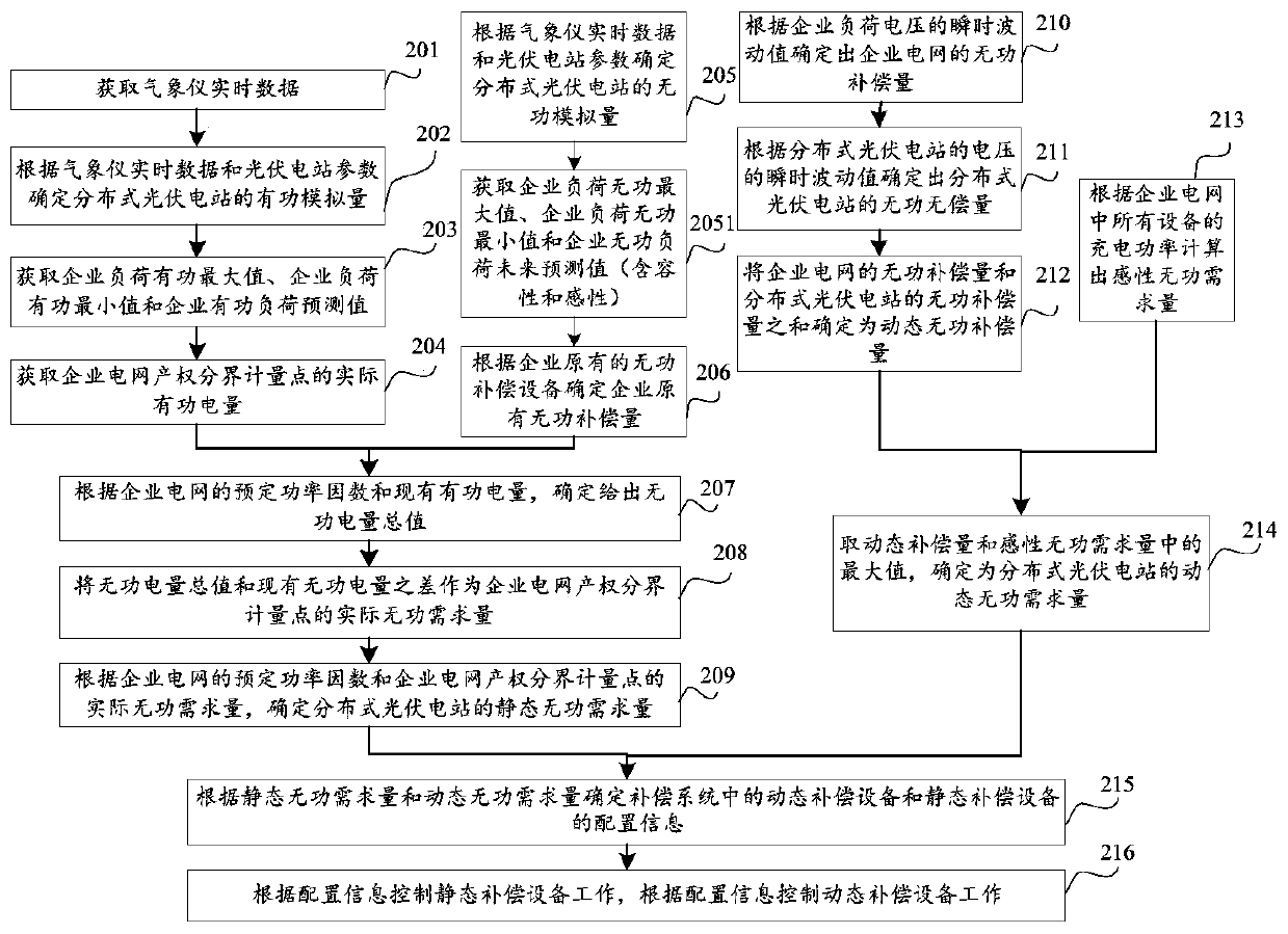
[0035] A flowchart of a control method for reactive power compensation of a distributed photovoltaic power plant provided by an embodiment of the present invention. The reactive power compensation control method of the distributed photovoltaic power station may include the following steps:

[0036] Step 101, according to the predetermined power factor of the enterprise grid, the existing active power and the existing reactive power, determine the actual reactive power demand of the property right boundary measurement point of the enterprise power grid.

[0037] Optionally, the existing active power includes the analog active power of the distributed photovoltaic power station, the maximum value of the active power of the enterprise loa...


PUM


Abstract

The invention discloses a reactive compensation control method for a distributed photovoltaic power station, and belongs to the field of photovoltaic power generation. The method comprises the steps:determining the actual reactive demand quantity of a property right boundary metering point of an enterprise power grid; determining a static reactive demand quantity of the distributed photovoltaic power station; determining a dynamic reactive compensation quantity according to an instantaneous fluctuation value of an enterprise load voltage and an instantaneous fluctuation value of a voltage ofthe distributed photovoltaic power station; calculating an inductive reactive demand quantity according to the charging power; determining the dynamic reactive demand quantity of the distributed photovoltaic power station according to the dynamic reactive compensation quantity and the inductive reactive demand quantity; determining the configuration information of dynamic compensation equipment and static compensation equipment according to the dynamic reactive compensation quantity and the inductive reactive demand quantity; and controlling the operation of the dynamic compensation equipmentand static compensation equipment according to the configuration information. The method solves a problem that the actual power factor does not meet the requirements after the distributed photovoltaicpower station is added. The method achieves the compensation for the reactive consumption of the distributed photovoltaic power station, and guarantees that the power factor of the property right boundary metering point of the enterprise power grid reaches the standard.

Description

technical field [0001] Embodiments of the present invention relate to the field of photovoltaic power generation, and in particular to a control method for reactive power compensation of a distributed photovoltaic power station. Background technique [0002] Loads in modern power systems include capacitive loads and inductive loads. In order to meet the requirements of power factor, corresponding compensation is required. Most electrical equipment such as transmission lines are inductive loads in most cases, and corresponding reactive power needs to be provided to such electrical equipment to reduce reactive power loss and power loss during the operation of such electrical equipment. [0003] With the development of distributed photovoltaic power stations, some enterprises will connect distributed photovoltaic power stations to the original power grid, and the reactive power compensation problems after the distributed photovoltaic power stations are connected to the original...

Claims


Application Information

Patent Timeline
Patent Type & Authority Patents(China)
IPC IPC(8): H02J3/18H02J3/38
CPCH02J3/18H02J3/383Y02E10/56Y02E40/30Y02P80/20
Inventor 吴峻杨先军马艳
Owner THE IT ELECTRONICS ELEVENTH DESIGN & RES INST SCI & TECHNOLOGICAL ENG
Why Eureka
Try Eureka