Method for configuring information, equipment and system

A technology for configuring information and indicating information, applied in the field of communication

Pending Publication Date: 2018-08-03
HUAWEI TECH CO LTD
View PDF9 Cites 21 Cited by
  • Summary
  • Abstract
  • Description
  • Claims
  • Application Information

AI Technical Summary

Problems solved by technology

This method is obviously no longer suitable for reference signal measurement and feedback based on analog narrow beams under 5G technology

Method used


Image

  • Method for configuring information, equipment and system
  • Method for configuring information, equipment and system
  • Method for configuring information, equipment and system

Examples


Embodiment 2

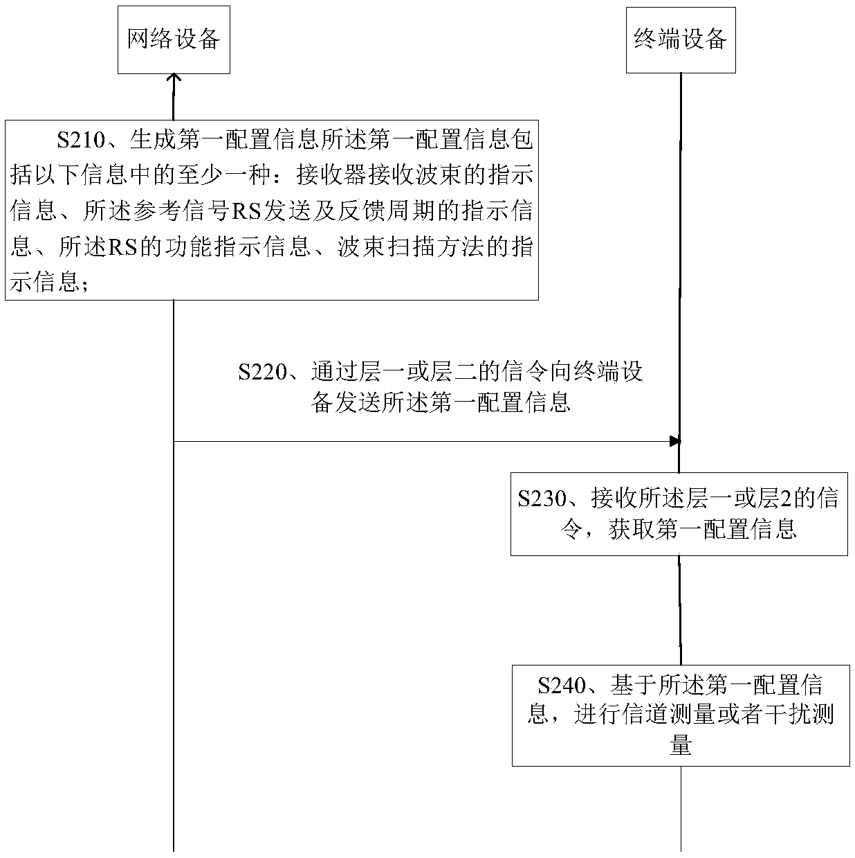
[0325] image 3 A schematic flowchart of a method 300 for configuring information according to an embodiment of the present application is shown. image 3 A network device in can be figure 1 network devices in ; terminal devices can be figure 1 in the terminal equipment.

[0326] S310. Divide the configuration information into first configuration information and second configuration information;

[0327] S320. Send the first configuration information to the terminal device through Layer 2 signaling;

[0328] S330. Send the second configuration information to the terminal device through Layer 1 or Layer 2 signaling;

[0329] S340. Receive the first configuration information from the network device, and acquire the first configuration information;

[0330] S350. Receive second configuration information from the network device, and acquire the second configuration information;

[0331] S360. Perform channel measurement or interference measurement or beam management accordin...

Embodiment 3

[0397] Figure 7 shows a schematic diagram of a network device, the network device can be applied to such as figure 1 system shown. The network device 700 includes a processor 710 , a memory 720 , a transceiver 730 , an antenna 740 , and a bus 750 .

[0398] Specifically, the processor 710 controls the operation of the network device 700, for example, controls the network device 700 to execute the above-mentioned part S210, and part S310. For details, refer to the description in the method embodiment, and details are not repeated here. The processor may be a general processor, a digital signal processor, an application specific integrated circuit, a field programmable gate array or other programmable logic devices.

[0399] The transceiver 730 is used to communicate with the terminal device, for example, may execute the above S220, S320, and S330 parts. For details, refer to the description in the method embodiments, and details are not repeated here. The transceiver 730 in...

Embodiment 4

[0404] Figure 8 It is a schematic block diagram of a terminal device 800 indicated by information according to an embodiment of the present application. The terminal equipment can be used as figure 1 system shown. The terminal device 800 includes a processor 810 , a memory 820 , a transceiver 830 , an antenna 840 , and a bus 850 .

[0405] Specifically, the processor 810 controls the operation of the terminal device 800, for example, controls the terminal device 800 to execute the above-mentioned part S240 and the above-mentioned part S360. For details, refer to the description in the method embodiment, and details are not repeated here. The processor may be a general processor, a digital signal processor, an application specific integrated circuit, a field programmable gate array or other programmable logic devices.

[0406] The transceiver 830 is used to communicate with the terminal device, for example, may execute the above S230, S340, and S350 parts. For details, refe...


PUM


Abstract

The embodiment of the invention provides a method for configuring information, equipment and a system. The method comprises the steps that network equipment generates first configuration information,wherein the first configuration information comprises at least one of the following information: terminal equipment received beam indication information, reference signal RS sending and channel stateinformation (CSI) feedback period indication information, RS function indication information, and beam scanning method indication information; and sending the first configuration information to the terminal equipment through a signal of a layer 1 or a layer 2. The embodiment of the invention provides a scheme of how to configure measurement information under the condition that a narrow beam technology is employed in a high frequency band.

Description

technical field [0001] The embodiments of the present application relate to the communication field, and more specifically, relate to a method, device and system for configuring measurement information. Background technique [0002] With the increasing shortage of low-frequency spectrum resources, high-frequency frequency bands (generally, frequency bands above 6GHz are high-frequency frequency bands, and frequency bands below 6GHz are low-frequency frequency bands) have become the main working frequency bands of 5G technology due to their rich spectrum resources. When using high-frequency bands, due to the large path loss of electromagnetic waves in the data transmission process and poor anti-fading performance, it is necessary to introduce narrow beam analog weighting technology. [0003] Since the coverage of the narrow beam is usually lower than 5 degrees, with the movement of the terminal equipment and the time-varying characteristics of the channel, the narrow beam det...

Claims


Application Information

Patent Timeline
Patent Type & Authority Applications(China)
IPC IPC(8): H04L5/00H04B17/30
CPCH04L5/0094H04L5/0096H04B17/30H04L41/08H04W16/28H04W72/046H04W72/0446H04L5/0023H04L5/0091H04L41/0806H04B7/0695H04B7/088H04B7/0626H04L5/0007H04L5/0048H04W72/541H04W72/542
Inventor 唐小勇王晓娜黄煌
Owner HUAWEI TECH CO LTD
Why Eureka
Try Eureka