Measurement capability reporting method, configuration methods, user equipment and base station

A technology of measurement capability and user equipment, applied in electrical components, wireless communication and other directions, can solve problems such as excessive air interface overhead and handover failure

Inactive Publication Date: 2018-08-03
BEIJING SAMSUNG TELECOM R&D CENT +1
View PDF0 Cites 34 Cited by
  • Summary
  • Abstract
  • Description
  • Claims
  • Application Information

AI Technical Summary

Problems solved by technology

[0015] The purpose of the present disclosure is to at least solve one of the above-mentioned technical defects. In particular, the present disclosure is to solve: the traditional method for reporting the measurement capability of each serving cell (that is, the UE reports to the base station traversally for each supported Frequency band or CA frequency band combination, ergodically for each possible measurement target, give its requirement for measurement interval on each operating frequency band (that is, whether measurement interval and / or NCSG is required)) Existing air interface overhead process Big problem; or after the network configures the frequency band or CA frequency band combination for the UE, the UE reports its measurement interval requirements on the frequency band or CA frequency band combination. There may be no measurement interval configured in a short period of time, resulting in handover The problem of failure, and the problem that the network must configure the measurement interval twice in a short period of time, and ensure the flexibility of UE implementation to the greatest extent

Method used


Image

  • Measurement capability reporting method, configuration methods, user equipment and base station
  • Measurement capability reporting method, configuration methods, user equipment and base station
  • Measurement capability reporting method, configuration methods, user equipment and base station

Examples


Embodiment Construction

[0162]Various embodiments of the present disclosure will be described in detail below with reference to the drawings and specific implementation methods. It should be noted that examples of various embodiments of the present disclosure are illustrated in the drawings, wherein the same or similar reference numerals designate the same or similar elements or elements having the same or similar functions throughout. The embodiments described below by referring to the figures are exemplary only for explaining the present disclosure and cannot be construed as limiting the present disclosure. In addition, for the sake of brevity, detailed descriptions of well-known technologies that are not directly related to the present disclosure are omitted to prevent confusion to the understanding of the present disclosure.

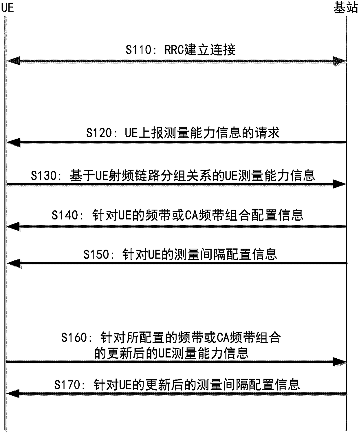
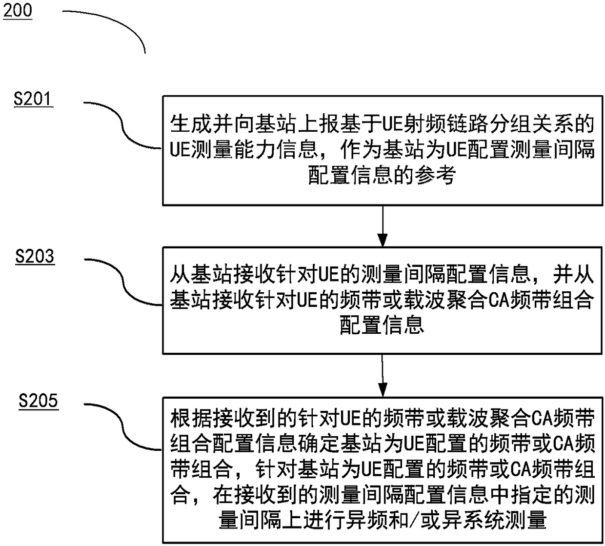
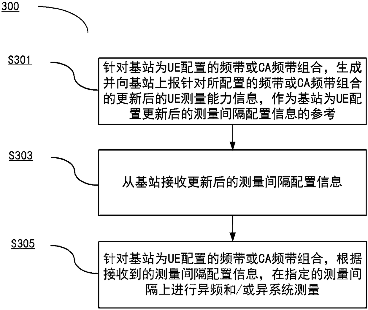
[0163] In order to achieve the above purpose of the present disclosure, exemplary embodiments of the present disclosure propose a solution for reporting and configuring mea...


PUM


Abstract

The invention provides a measurement capability reporting method performed at UE (User Equipment). The method comprises the steps of generating and reporting UE measurement capability information based on a UE radio frequency link grouping relationship to a base station, as a reference for the base station to configure measurement gap configuration information for the UE; receiving the measurementgap configuration information for the UE from the base station, and receiving band or carrier aggregation (CA) band combination configuration information for the UE from the base station; and determining band or CA band combination configured for the UE by the base station according to the received band or carrier aggregation (CA) band combination configuration information for the UE, and for theband or CA band combination configured for the UE by the base station, carrying out inter-frequency measurement and/or inter-radio access technology measurement on a measurement gap appointed in thereceived measurement gap configuration information. The invention also provides a measurement gap configuration method performed at the base station, a measurement gap demand updating method performedat the UE, an updated measurement gap configuration method performed at the base station, and the corresponding user equipment and base station.

Description

technical field [0001] The present disclosure relates to the technical field of wireless communication, and in particular, the present disclosure relates to a method for reporting and configuring a measurement capability, as well as a corresponding user equipment and a base station. Background technique [0002] In mobile communication systems, cell reselection and handover are important functions for meeting mobility requirements. In order to realize cell reselection smoothly, user equipment (User Equipment, UE for short) needs to measure the signal quality of different cells, so as to select a suitable cell to camp on. After the UE establishes a connection with the network in a certain cell, the UE still needs to measure the signal quality of its neighboring cells in order to select a suitable cell for handover, so as to meet the mobility requirements of communication. [0003] The specific process for the UE to complete the signal quality measurement in the connected sta...

Claims


Application Information

Patent Timeline
Patent Type & Authority Applications(China)
IPC IPC(8): H04W24/00H04W24/10
CPCH04W24/00H04W24/10
Inventor 王翯周续涛
Owner BEIJING SAMSUNG TELECOM R&D CENT
Why Eureka
Try Eureka