Methods and apparatuses for monitoring the functionality of redundantly interconnected contacts

A contact and function technology, applied in measuring devices, instruments, detailed information of electromagnetic relays, etc., can solve problems such as expansion of installation space, load or functional danger, restrictions, etc., to achieve the effect of high monitoring flexibility and high flexibility

Active Publication Date: 2018-08-03
PEPPERL FUCHS GMBH
View PDF9 Cites 0 Cited by
  • Summary
  • Abstract
  • Description
  • Claims
  • Application Information

AI Technical Summary

Problems solved by technology

However, this leads to significant limitations regarding the selection of relays or contacts in a single application to the positively driven contacts or relays
[0007] Minimizing risk through redundancy has the disadvantage that failures based on the same cause (i.e. common cause) are still potentially dangerous to the load or function to be protected
Adding redundancy can provide a slight improvement in safety, however, due to limited installation space, adding redundancy is not always possible
[0008] The use of positively driven contacts or relays generally provides an improvement, however, the implementation of positively driven contacts or relays requires an enlarged installation space and limits the selection possibilities regarding the components of the device
[0009] Known methods and devices for monitoring the function of redundant interconnect contacts require complex circuits and often large installation spaces to provide a high level of risk minimization

Method used


Image

  • Methods and apparatuses for monitoring the functionality of redundantly interconnected contacts
  • Methods and apparatuses for monitoring the functionality of redundantly interconnected contacts
  • Methods and apparatuses for monitoring the functionality of redundantly interconnected contacts

Examples


Embodiment Construction

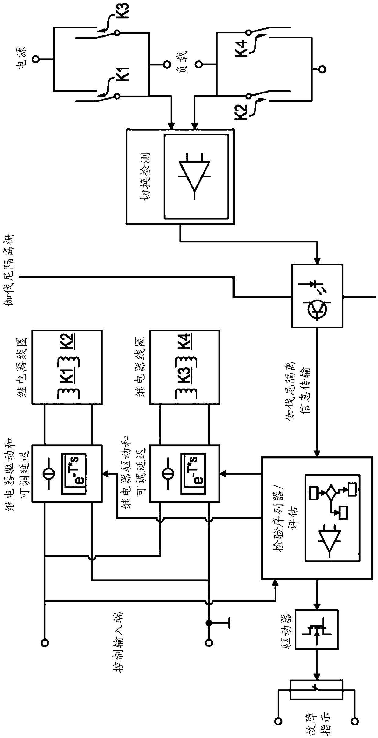
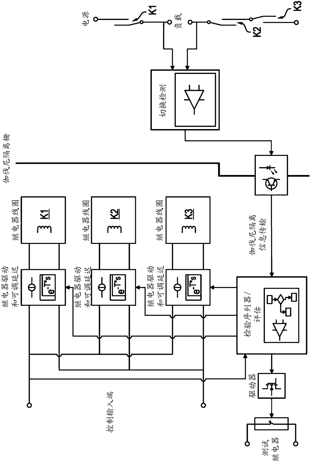
[0047] figure 1 Illustrations of methods and / or apparatuses according to embodiments of the invention are shown within block diagrams. In this embodiment, n=2 redundant channels are realized for the all-pole switching process, wherein channel CH1 is realized by switch K1 and switch K2, and switch K1 and switch K2 are realized by switches K1 and switch K2 to activate the relay coil. Channel CH2 is implemented by switches K3 and K4, which are energized by relay coils for these switches K3 and K4. The relay coils for activating switches K1, K2, K3 and K4 are in figure 1 The middle part of is shown.

[0048] figure 1 The layout of the left part and figure 1 The arrangement of the right part is isolated by Galvani. Control inputs include relay drivers with adjustable delays for switching or energizing relay coils. Switches K1, K2, K3 and K4 are provided for providing electrical connection between the power source and the load.

[0049] Switching detection circuits are provi...


PUM


Abstract

For providing a very simple and reliable monitoring of the functionality of contacts together with a high flexibility of selection of the contacts a method for monitoring the functionality of redundantly interconnected contacts is provided, preferably within a load current circuit, wherein said n contacts, n = 2, provide an electrical connection between a power supply and a load, wherein said n contacts are switchable by a controller and wherein each of said n contacts is designed for providing the electrical connection between the power supply and the load all alone. The method is characterized in that the controller switches on said n contacts during n subsequent activations according to a defined schedule according to which at the first of said n subsequent activations one of said n contacts is switched on first and the remaining n-1 contacts are switched on afterwards, so that a verification regarding the functionality of said one of said n contacts is possible, and according to which at each of the n-1 remaining subsequent activations a further one of said n contacts is switched on first with switching on of the remaining n-1 contacts afterwards, so that after said n subsequent activations each of said n contacts has once been switched on first and a verification regarding the functionality of each of said n contacts is possible. Further, a corresponding method for subsequent deactivations and corresponding apparatuses are provided.

Description

technical field [0001] The present invention relates to a method for monitoring the function of redundant interconnection contacts, preferably used in load current circuits, wherein said n (n=2,...,) contacts provide a connection between power supply and load wherein the n contacts can be switched by the controller, and wherein each of the n contacts is designed to individually provide an electrical connection between the power source and the load. Furthermore, the invention relates to a corresponding device for monitoring the function of redundant interconnection contacts. [0002] In general, the invention relates to the field of safety-related systems or safety-related communication systems in which, for example, reliable switching on and / or switching off of functions or loads is necessary. Background technique [0003] From US 2012 / 0229938 A1 a method and a device are known for monitoring the function of redundant interconnection contacts. This document shows a safety-...

Claims


Application Information

Patent Timeline
Patent Type & Authority Applications(China)
IPC IPC(8): H01H47/00
CPCH01H47/004H01H47/002G01R31/3278H01H50/08H01H50/54
Inventor 丹尼尔·索尔海默弗里德里希·菲斯
Owner PEPPERL FUCHS GMBH
Why Eureka
Try Eureka