Automatic cutting device

A technology of automatic cutting device and transmission plate, which is applied in metal processing and other directions, can solve problems such as hidden dangers, complicated operation and safety, and achieve the effect of easy operation.

Inactive Publication Date: 2018-08-07
NANJING HANXIYUE AUTOMATION TECH CO LTD
View PDF0 Cites 2 Cited by
  • Summary
  • Abstract
  • Description
  • Claims
  • Application Information

AI Technical Summary

Problems solved by technology

However, the existing cutting device is not only complicated to operate, but also unable to adapt to the cutting of different workpieces, and there are potential safety hazards in the operation process, so that there are certain limitations in use.

Method used


Image

  • Automatic cutting device
  • Automatic cutting device
  • Automatic cutting device

Examples


Embodiment Construction

[0017] The following will clearly and completely describe the technical solutions in the embodiments of the present invention with reference to the accompanying drawings in the embodiments of the present invention. Obviously, the described embodiments are only some, not all, embodiments of the present invention. All other embodiments obtained by persons of ordinary skill in the art based on the embodiments of the present invention belong to the protection scope of the present invention.

[0018] According to an embodiment of the present invention, an automatic cutting device is provided.

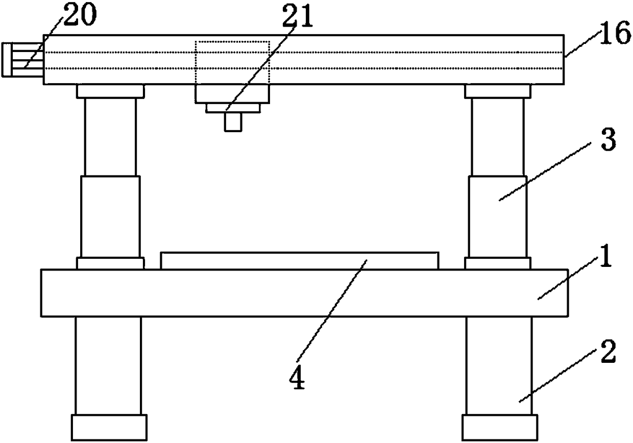
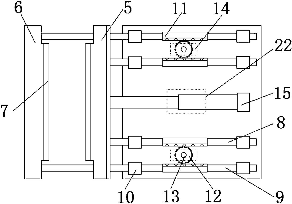
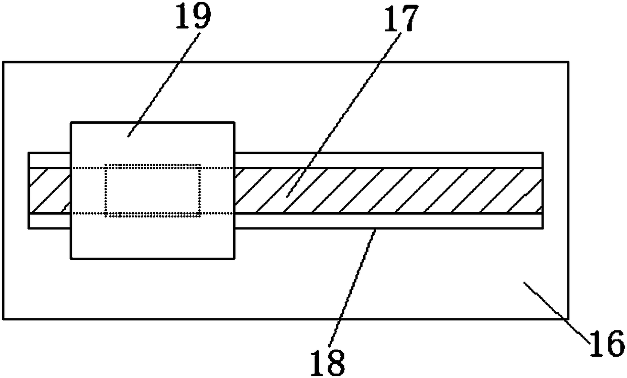
[0019] Such as Figure 1-3 As shown, the automatic cutting device according to the embodiment of the present invention includes an operation table 1, the bottom end of the operation table 1 is provided with a column 2, and the top end of the operation table 1 is provided with a telescopic cylinder 3, which is located at the telescopic A base plate 4 is arranged between the cylinders 3, and ...


PUM


Abstract

The invention discloses an automatic cutting device. The automatic cutting device comprises an operation platform, wherein vertical columns are arranged at the bottom end of the operation platform; telescopic cylinders are arranged at the top end of the operation platform; a base plate is arranged between the telescopic cylinders; the bottom end of the base plate is fixedly connected with the operation platform; a first clamping plate and a second clamping plate are respectively arranged at one side of the base plate, and the close sides of the first clamping plate and the second clamping plate are respectively provided with antiskid strips. The automatic cutting device disclosed by the invention has the beneficial effects that due to a rotary shaft under the action of a first rotary motor, convenience is brought for transmission of a first sliding rod and a second sliding rod by matching between rotary teeth and a clamping rack, the first sliding rod and the second sliding rod facilitate the first clamping plate and the second clamping plate to clamp materials, and a controller is matched with telescopic rods to limit transmission of the first clamping plate; in addition, due to an ejecting plate under the action of the telescopic cylinders, convenience is brought for a transmission plate of the rotary roll in the top plate under the action of a second rotary motor to cut thematerials; the automatic cutting device not only is simple in operation, but also can adapt to the need of operation under different environments.

Description

technical field [0001] The invention relates to the technical field of mechanical equipment, in particular to an automatic cutting device. Background technique [0002] With the development of the modern mechanical processing industry, the requirements for cutting quality and precision are constantly improving, and the requirements for improving production efficiency, reducing production costs, and highly intelligent automatic cutting functions are also increasing. The development of CNC cutting machines must adapt to the requirements of the development of modern machining industry. Cutting machine is divided into flame cutting machine, plasma cutting machine, laser cutting machine, water cutting and so on. The laser cutting machine has the fastest efficiency, the highest cutting precision, and the cutting thickness is generally small. The cutting speed of the plasma cutting machine is also very fast, and the cutting surface has a certain slope. The flame cutting machine ...

Claims


Application Information

Patent Timeline
Patent Type & Authority Applications(China)
IPC IPC(8): B26D1/04B26D7/04B26D5/08B26D5/04
CPCB26D1/04B26D5/04B26D5/086B26D7/04
Inventor 李馨嫔王健
Owner NANJING HANXIYUE AUTOMATION TECH CO LTD
Why Eureka
Try Eureka