Rotating disk type automobile stepped shaft storage device

A storage device and a stepped shaft technology, applied in the field of auto parts, can solve the problems such as dimension deviation of the stepped shaft of the automobile, bending deformation of the stepped shaft, bump damage on the surface of the stepped shaft of the automobile, etc., and achieve the effect of good storage conditions.

Inactive Publication Date: 2018-08-07
HUZHOU ANRUINENG HYDRAULICPNEUMATIC TECH CO LTD
View PDF10 Cites 3 Cited by
  • Summary
  • Abstract
  • Description
  • Claims
  • Application Information

AI Technical Summary

Problems solved by technology

[0002] Automobile stepped shaft is a relatively common and important part in automobile manufacturing. After the mass-produced automobile stepped shaft is manufactured, it is generally placed directly on the ground or on a simple shelf, which is easy to cause the surface of the automobile stepped shaft. Collision damage, and in such a stacking method, the car ladder shaft is generally placed horizontally, especially the longer car ladder shaft is prone to bending deformation, resulting in a series of quality problems such as the size deviation of the car ladder shaft
[0003] Chinese Patent Authorization Announcement No. CN 203903092 U, date of authorized announcement is 2014.10.29, titled "A Drive Shaft Placement Rack", which discloses a shaft-type workpiece placed vertically in the positioning hole of the layered rack, and divided into The distance between the shelves can be adjusted to suit the length of the car ladder shaft. This kind of shelf is limited by the size of the positioning hole, and the size of the shaft workpiece that can be stored is relatively single. In addition, the car ladder shaft is accessed vertically. It is easy to interfere with the layered frame, which is inconvenient to use

Method used


Image

  • Rotating disk type automobile stepped shaft storage device
  • Rotating disk type automobile stepped shaft storage device
  • Rotating disk type automobile stepped shaft storage device

Examples


Embodiment Construction

[0021] The present invention will be further described below in conjunction with the accompanying drawings and specific embodiments.

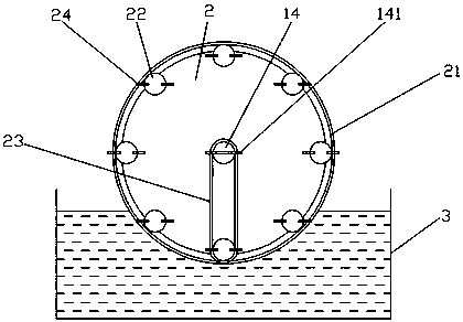
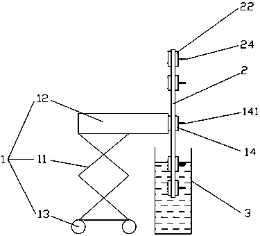
[0022] Such as Figure 1 to Figure 3 As shown in , a turntable type car stepped shaft storage device, including

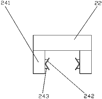
[0023] Base 1 and rotating disk 2, base comprises elevating frame 11, the mounting shaft 12 that is located at the top of elevating frame and some universal wheels 13 that are located at the bottom of elevating frame, is provided with the motor that is used to drive mounting shaft to rotate on the mounting shaft, and rotating disc Rotation is arranged on the installation shaft, and the base is provided with a fixed sprocket 14, and the fixed sprocket is fixed on the installation shaft, and the bottom of the rotating disk is provided with an oil pool 3 for oiling the automobile stepped shaft. The turntable is provided with an endless chain 21 arranged coaxially with the turntable and a number of movable sprockets 22 engaged with the...


PUM


Abstract

The invention discloses a rotating disk type automobile stepped shaft storage device which is characterized in that automobile stepped shafts can be vertically and orderly placed, the size universality of the stored automobile stepped shafts is good, and the automobile stepped shafts are easily stored and taken out. The device comprises a base and a rotating disk rotatably arranged on the base, anannular chain and a plurality of movable chain wheels engaged with the annular chain are arranged on the rotating disk, the annular chain and the rotating disk are coaxially arranged, the movable chain wheels are positioned on the inner side of the annular chain, the movable chain wheels are uniformly distributed along a circumferential direction of the rotating disk, a fixed chain wheel is arranged on the base and positioned at the center of the rotating disk, the fixed chain wheel is connected with one movable chain wheel through a chain, a clamping plate is horizontally arranged on the movable chain wheels and comprises two opposite clamping portions, and the clamping portions are horizontally and slidably arranged on the movable chain wheels. The device can be used for vertically placing the automobile stepped shaft with different sizes, the automobile stepped shafts are conveniently stored and taken out, oil can be automatically fed through an oil tank, and storage is facilitated.

Description

technical field [0001] The invention relates to the field of auto parts, in particular to a turntable-type auto stepped shaft storage device. Background technique [0002] Automobile stepped shaft is a relatively common and important part in automobile manufacturing. After the mass-produced automobile stepped shaft is manufactured, it is generally placed directly on the ground or on a simple shelf, which is easy to cause the surface of the automobile stepped shaft. Bump damage, and in such a stacking method, the car ladder shaft is generally placed horizontally, especially the longer car ladder shaft is prone to bending deformation, resulting in a series of quality problems such as the size deviation of the car ladder shaft. [0003] Chinese Patent Authorization Announcement No. CN 203903092 U, date of authorized announcement is 2014.10.29, titled "A Drive Shaft Placement Rack", which discloses a shaft-type workpiece placed vertically in the positioning hole of the layered r...

Claims


Application Information

Patent Timeline
Patent Type & Authority Applications(China)
IPC IPC(8): B65G29/00
CPCB65G29/00
Inventor 杨海斌蒋锦邦刘辉
Owner HUZHOU ANRUINENG HYDRAULICPNEUMATIC TECH CO LTD
Why Eureka
Try Eureka