
Experimental device and method based on characteristic study of metal particle movvement

A technology of metal particles and motion characteristics, applied in the direction of using optical methods to test, test dielectric strength, analyze materials, etc., can solve the problems of gas decomposition, increase the difficulty of detection and prevention, and decrease the dielectric strength, reduce investment, Low performance requirements and the effect of avoiding measurement errors

Pending Publication Date: 2018-08-07
SHENYANG POLYTECHNIC UNIV
View PDF0 Cites 0 Cited by
  • Summary
  • Abstract
  • Description
  • Claims
  • Application Information

AI Technical Summary

Problems solved by technology

However, GIS / GIL will produce some metal debris or particles during transportation, assembly, and operation. According to the statistics of reliable operation, most of the faults inside electrical equipment are caused by metal particles in electrical equipment. Free conductive particles Existence will cause SF 6 Dielectric strength drops up to more than 80%
The metal particles move freely in the insulating cavity, and the resulting electric field distortion will bring a series of insulation problems: 1. The maximum and minimum values ​​of the electric field strength are at the fixed particles, and the field strength distortion near the metal particles is easy to cause The gas around the particles decomposes; 2. The free metal particles may roll or jump under the action of the electric field environment, and its movement is largely random, which increases the difficulty of detection and prevention; 3. Attached metal particles The insulator's flashover along the surface deteriorates the dielectric strength of GIS / GIL more seriously than the case of air gap breakdown

Method used


Image

  • Experimental device and method based on characteristic study of metal particle movvement
  • Experimental device and method based on characteristic study of metal particle movvement

Examples


Embodiment Construction

[0031] The technical solutions of the present invention will be described in detail below in conjunction with specific implementation methods.

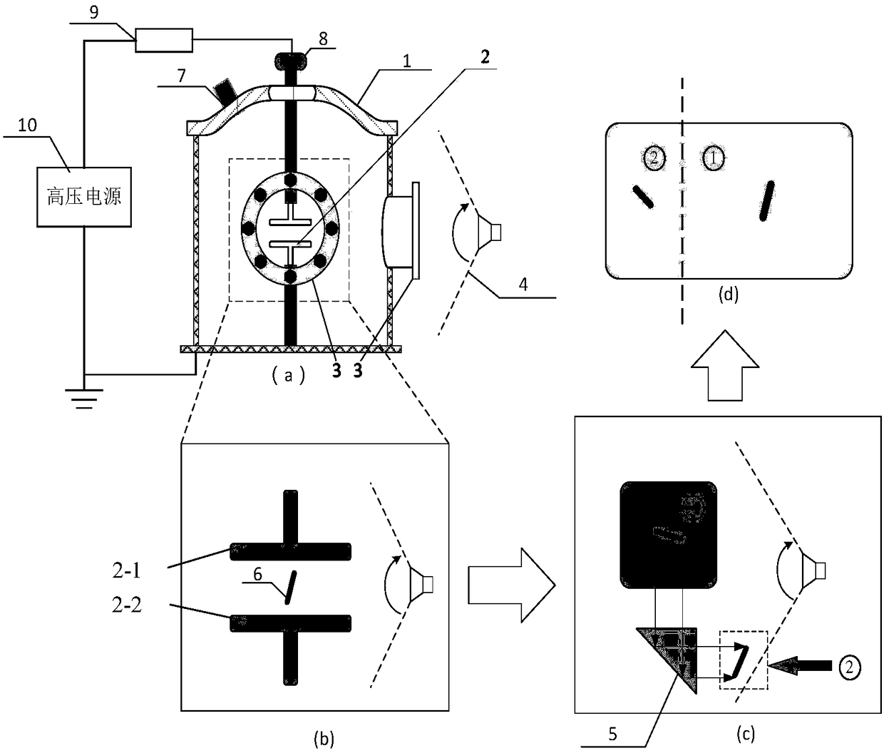
[0032] This embodiment provides a figure 1 The experimental device based on the research on the motion characteristics of metal particles shown in (a) to (d) includes a sealed gas chamber 1 and an electrode module 2; the electrode module 2 is installed inside the sealed gas chamber 1, and the electrode module 2 consists of an upper plate 2-1 and the lower pole plate 2-2, the upper pole plate 2-1 is connected with the high-voltage power supply 10 through the protection resistor 9, the lower pole plate 2-2 is connected with the shell of the sealed air chamber 1, and the shell is grounded. The upper pole plate 2-1 and the lower pole plate 2-2 are arranged in parallel or at an included angle.

[0033] Quartz windows 3 are respectively installed on the front and sides of the sealed gas chamber 1, which are respectively aligned with the ce...


PUM


Abstract

The invention provides an experimental device and a method based on characteristic study of metal particle movvement. The experimental device comprises a sealing air chamber and an electrode module, wherein the electrode module is arranged in the sealing air chamber, and consists of an upper electrode plate and a lower electrode plate; the upper electrode plate is connected with a high-voltage power source through a protection resistor, and the lower electrode plate is connected with an outer casing of the sealing air chamber; the outer casing is grounded. The method comprises the following steps of checking whether the equipment of each part is complete or not; placing the metal particles between the upper electrode plate and the lower electrode plate; filling air into the sealing air chamber to the required pressure; adjusting the distance between the two electrode plates, engaging the high-pressure power source, and increasing the voltage until the metal particles are moved; observing whether the metal particles can bounce onto the upper electrode of the electrode module or not; when the metal particles cannot bounce onto the upper electrode, adjusting the distance between the upper electrode plate and the lower electrode plate until the metal particles can bounce onto the upper electrode plate; when the metal particles are moved to the rightmost side of the upper electrodeplate, finishing the experiment. The experimental device has the advantages that the influence by the air environment is avoided, the device can work under any air environment, and the problem of synchronizing of image signal acquistion at two directions is solved.

Description

technical field [0001] The invention relates to the technical field of high-voltage transmission lines and insulation, in particular to an experimental device and method based on the research on the motion characteristics of metal particles. Background technique [0002] GIS / GIL equipment has been applied since the 1960s and 1970s and has been widely used all over the world, and has great application prospects in the fields of UHV power transmission and offshore large-scale wind power transmission. However, GIS / GIL will produce some metal debris or particles during transportation, assembly, and operation. According to the statistics of reliable operation, most of the faults inside electrical equipment are caused by metal particles in electrical equipment. Free conductive particles Existence will cause SF 6 Dielectric strength drops up to more than 80%. The metal particles move freely in the insulating cavity, and the resulting electric field distortion will bring a series ...

Claims


Application Information

Patent Timeline
IPC IPC(8): G01R31/12G01N15/00
CPCG01R31/1218G01N15/00
Inventor 林莘高佳杨明智翟芷萱李晓龙温苗葛凡刘鹏飞
Owner SHENYANG POLYTECHNIC UNIV
Learn More