Constant-voltage output circuit of two-stage input inverter power supply

A technology of inverter power supply and constant voltage output, which is applied in the direction of converting DC power input to DC power output, output power conversion devices, electrical components, etc., and can solve the problem of narrow pulse width, burning of high-voltage power consumption parts, and boost output parts Problems such as high voltage, achieve fast response, high reliability, and reduce strict requirements

Active Publication Date: 2018-08-07
SHUNDE POLYTECHNIC
View PDF0 Cites 1 Cited by
  • Summary
  • Abstract
  • Description
  • Claims
  • Application Information

AI Technical Summary

Problems solved by technology

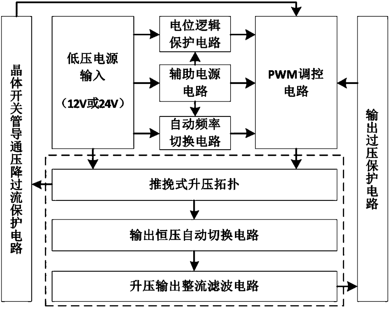
For these topologies, the input voltage is limited to a relatively narrow range to ensure a fixed transformation ratio. When the input voltage changes greatly, the voltage of the boost output part will be too high, which may burn the high-voltage power part.
Although the output voltage is too high, the purpose of setting the voltage output can be achieved through PWM modulation, but this will reduce the power conversion efficiency (at this time, the pulse width of the PWM driving signal is very narrow, resulting in a lower power conversion rate)
Therefore, in the coupling scheme of multi-input switching converters, each input corresponds to its own power conversion circuit or passes through a more complex control circuit. Although this is suitable for different input voltages, the cost of the system solution is high and the economy is reduced.

Method used


Image

  • Constant-voltage output circuit of two-stage input inverter power supply
  • Constant-voltage output circuit of two-stage input inverter power supply
  • Constant-voltage output circuit of two-stage input inverter power supply

Examples


Embodiment Construction

[0017] Embodiments of the present invention are described in detail below, examples of which are shown in the accompanying drawings, wherein the same or similar reference numerals designate the same or similar elements or elements having the same or similar functions throughout. The embodiments described below by referring to the figures are exemplary only for explaining the present invention and should not be construed as limiting the present invention.

[0018] In describing the present invention, it is to be understood that the terms "central", "lateral", "upper", "lower", "left", "right", "vertical", "horizontal", "inner", The orientation or positional relationship indicated by "outside" is based on the orientation or positional relationship shown in the drawings, which is only for the convenience of describing the present invention and simplifying the description, rather than indicating or implying that the referred device or element must have a specific orientation, Cons...


PUM


Abstract

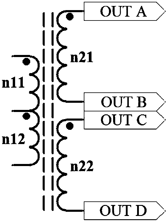
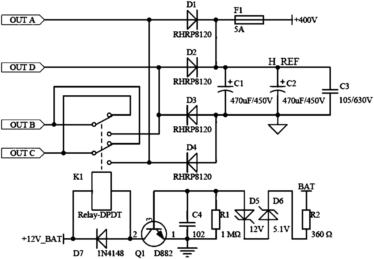
The invention discloses a constant-voltage output circuit of a two-stage input inverter power supply. The constant-voltage output circuit comprises a push-pull transformer, a changeover switch K1, a switch driving circuit and a rectifying and filtering circuit; the push-pull transformer is connected with the rectifying and filtering circuit through the changeover switch K1; the input windings of the push-pull transformer comprise two windings, wherein the two windings have the same number of turns and are provided with center taps; the output windings of the push-pull transformer are two independent windings with the same number of turns; the normally closed contacts of the changeover switch K1 are respectively connected with the B port and C port of the two output windings of the push-pull transformer, the normally open contacts of the changeover switch K1 are respectively connected with the A port and D port of the two output windings of the push-pull transformer, and therefore, whena relay armature is in a released state, the ports of the two output windings connected with the normally closed contacts are an internal short-circuited state, and are not connected with the rectifying and filtering circuit, and the two output windings of the push-pull transformer achieve series output; and when the relay armature is in a pull-in state, the two output windings of the push-pull transformer achieve parallel output. According to the constant-voltage output circuit of the invention, one push-pull transformer can be used either for 12V or 24V input, so that constant-voltage output can be achieved.

Description

technical field [0001] The invention relates to the technical field of constant voltage output circuit design, in particular to a constant voltage output circuit of a dual-stage input inverter power supply. Background technique [0002] With the rise of green renewable energy such as photovoltaic power generation, the application of inverter power supply and related research are becoming more and more extensive and in-depth. It is widely used in home, company server, satellite relay station and even aerospace industry. The boost circuit is a key part of the inverter power supply, and its key indicators such as working stability, safety, and response sensitivity all affect the normal operation of the entire inverter power supply system. [0003] In the boost circuit, the commonly used methods are: Push-Pull (push-pull topology), Weinberg Circuit (Weinberg circuit topology), Half-Bridge (half-bridge topology), Full-Bridge (full-bridge topology) ) and so on, the most commonly...

Claims


Application Information

Patent Timeline
Patent Type & Authority Applications(China)
IPC IPC(8): H02M3/337
CPCH02M3/3378
Inventor 宋玉宏刘加松
Owner SHUNDE POLYTECHNIC
Why Eureka
Try Eureka