

Complete-set aging test system and method for circuit board of automobile motor controller
A technology of motor controller and aging test, which is applied in the direction of electronic circuit testing, instruments, measuring electronics, etc. It can solve the problems of unable to test the aging of motor controller circuit boards, etc., so as to facilitate fault location and traceability, reduce human intervention, and improve the process The effect of work efficiency
- Summary
- Abstract
- Description
- Claims
- Application Information
AI Technical Summary
Problems solved by technology
Method used
Image

Examples
Embodiment 1
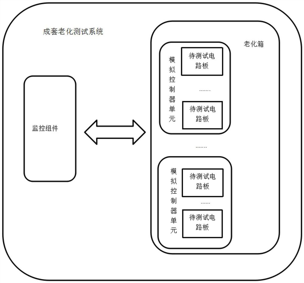
[0044] like figure 1 As shown, the present invention discloses a complete set of aging test system for circuit boards of automobile motor controllers, including: a monitoring component and an aging box connected to the monitoring component. A complete set of analog control units for aging multiple circuit boards to be tested;
[0045] The monitoring component is used to control the analog control unit to provide the working signals required for the aging test of multiple circuit boards to be tested, and send the read test messages generated by the multiple circuit boards to be tested according to the working signals to the monitoring component; The document at least includes serial numbers of multiple circuit boards to be tested and corresponding fault information of multiple circuit boards to be tested;
[0046] The monitoring component is also used for receiving test messages from the analog control unit, and analyzing the test messages to determine the corresponding aging ...
Embodiment 2
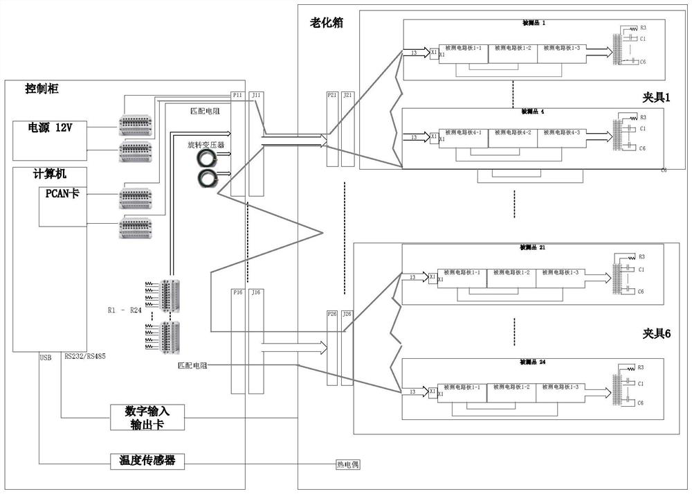
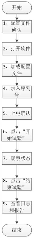
[0053] Embodiment two is the preferred embodiment of embodiment one, and its difference with embodiment is that, the specific structure of the complete aging test system of the circuit board of automobile motor controller has been refined and optimized, and its tested The specific process has been refined and optimized:
[0054] The complete aging test system of the circuit board of the automobile motor controller in the present embodiment is as follows: figure 2 As shown, it includes a control cabinet and an aging box connected to the control cabinet. A power supply component, a monitoring component and a rotary transformer are installed in the control cabinet, and a temperature sensor, an analog control unit and multiple load circuits are arranged in the aging box; in this embodiment The upper computer and the control card are used as the monitoring components, and the power supply components use a 12V DC regulated power supply (DC, DC voltage-stabilized source). Also conn...
PUM
 Abstract
Description
Claims
Application Information