
Linear cutting gear-aligning clamp of reducer gear

A wire cutting and reducer technology, applied in the direction of manufacturing tools, electric processing equipment, metal processing equipment, etc., can solve the problems of reducing the use efficiency of the fixture, affecting the gear processing, poor universality of the fixture, etc., to improve the use efficiency and ensure stability. , to ensure the effect of normal processing

Pending Publication Date: 2018-08-10
盐城市金洲机械制造有限公司
View PDF0 Cites 0 Cited by
  • Summary
  • Abstract
  • Description
  • Claims
  • Application Information

AI Technical Summary

Problems solved by technology

[0003] The purpose of the present invention is to provide a tooth-aligning jig for wire cutting gear of a reducer, to solve the problem that the gear of the reducer on the market is not easy to fix during the wire cutting process proposed by the above-mentioned background technology, which affects the processing of the gear, and the existing jig It is a gear corresponding to a single shaft hole diameter. If you need to process gears with different shaft hole diameters, you need to replace the corresponding fixtures, resulting in poor versatility of the fixtures, which in turn reduces the use efficiency of the fixtures.

Method used


Image

  • Linear cutting gear-aligning clamp of reducer gear
  • Linear cutting gear-aligning clamp of reducer gear
  • Linear cutting gear-aligning clamp of reducer gear

Examples


Embodiment Construction

[0018] The following will clearly and completely describe the technical solutions in the embodiments of the present invention with reference to the accompanying drawings in the embodiments of the present invention. Obviously, the described embodiments are only some, not all, embodiments of the present invention. Based on the embodiments of the present invention, all other embodiments obtained by persons of ordinary skill in the art without making creative efforts belong to the protection scope of the present invention.

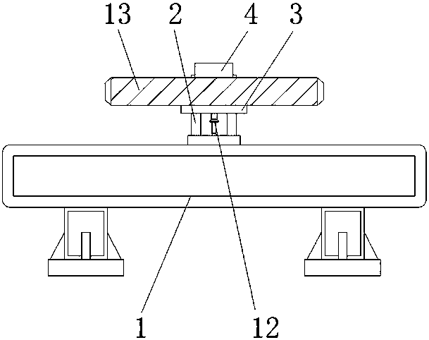
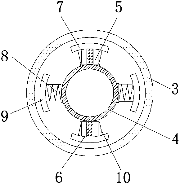
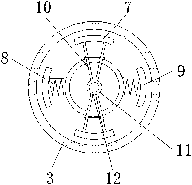
[0019] see Figure 1-3 , the present invention provides a technical solution: a wire cutting tooth alignment fixture for gears of reducers, including a base 1, a support frame 2, a cushion block 3, a mandrel 4, a connecting plate 5, a chute 6, and a first block 7 , connecting spring 8, second block 9, pull rod 10, connecting shaft 11, connecting rod 12 and gear 13, support frame 2 is fixed on the top of base 1, and the top of support frame 2 is connected with ...


PUM


Abstract

The invention discloses a linear cutting gear-aligning clamp of a reducer gear. The linear cutting gear-aligning clamp comprises a base, connecting springs and pull rods. A supporting frame is fixed to the upper portion of the base, and a cushion block is connected to the top of the supporting frame. A mandrel is arranged in the cushion block, and connecting plates are mounted on the upper side and the lower side of the mandrel. Sliding grooves are formed in the connecting plates, and first clamping blocks are connected to the upper portions of the sliding grooves. The connecting springs and the mandrel are connected, and second clamping blocks are arranged on the left sides of the connecting springs and fixed to the tops of the pull rods. A connecting shaft is connected to the bottoms ofthe pull rods, and a connecting rod is arranged at the bottom of the connecting shaft. The gear is arranged above the cushion block. According to the linear cutting gear-aligning clamp of the reducergear, the cushion block is arranged, the diameter of the cushion block is larger than the diameter of a middle hole, namely a shaft hole, of the gear, thus the falling phenomenon can be avoided duringgear placing, and normal machining of the gear is guaranteed.

Description

technical field [0001] The invention relates to the technical field of fixtures, in particular to a wire-cut tooth alignment fixture for gears of reducers. Background technique [0002] The processing of reducer gears usually adopts wire cutting. Wire cutting is widely used in the mechanical field. Wire cutting can also be divided into many types. However, the existing reducer gears are not easy to fix during the wire cutting process, which affects the processing of gears. , and the existing fixtures are gears corresponding to a single shaft hole diameter. If you need to process gears with different shaft hole diameters, you need to replace the corresponding fixtures, resulting in poor versatility of the fixtures, which in turn reduces the efficiency of the fixtures. Therefore, we propose A tooth-aligning jig for wire cutting gears of a reducer is provided to solve the above-mentioned problems. Contents of the invention [0003] The purpose of the present invention is to ...

Claims


Application Information

Patent Timeline
IPC IPC(8): B23H11/00B23H7/02
CPCB23H7/02B23H11/003
Inventor 张亦标董吉初
Owner 盐城市金洲机械制造有限公司
Learn More