A prefabricated box girder steel bar binding mold and its installation method

A technology for tying steel bars and box beams, applied in manufacturing tools, ceramic molding machines, etc., can solve the problems of difficulty in controlling the pass rate of steel bar protective layer, affecting the appearance of finished products, pollution of the bottom plate, etc., to improve the binding speed and binding quality, and easy to operate. , the effect of avoiding pollution

Active Publication Date: 2019-10-08
ZHEJIANG BADA TUNNEL ENG CO LTD
View PDF7 Cites 0 Cited by
  • Summary
  • Abstract
  • Description
  • Claims
  • Application Information

AI Technical Summary

Problems solved by technology

Welding is required when tying the steel bars of the bottom web, which will inevitably pollute the bottom plate and affect the appearance of the finished product; the positioning of the steel bars is mainly controlled by visual inspection, ruler measurement, drawing points, and strip lines, which requires heavy workload and low precision. It is difficult to control the qualification rate of steel bar cover of prefabricated box girder

Method used


Image

  • A prefabricated box girder steel bar binding mold and its installation method
  • A prefabricated box girder steel bar binding mold and its installation method
  • A prefabricated box girder steel bar binding mold and its installation method

Examples


Embodiment Construction

[0022] The following are preferred embodiments of the present invention, but the protection scope of the present invention is not limited thereby.

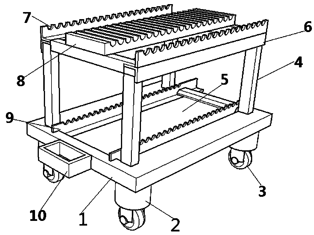
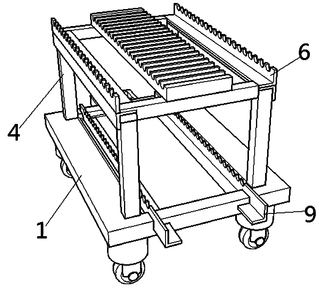
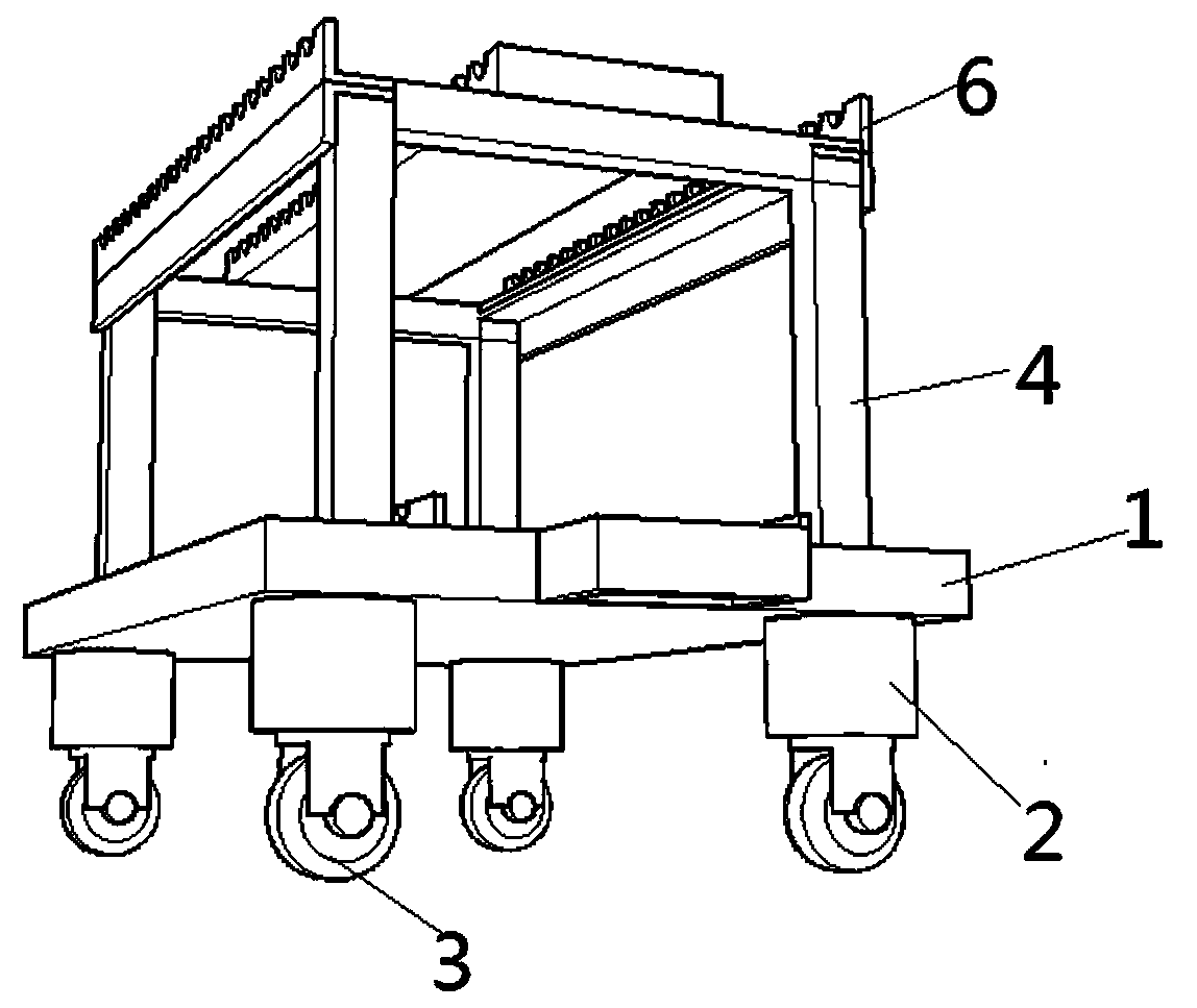
[0023] As shown in the figure, a prefabricated box girder reinforcement tying mold includes a bottom plate 1, a telescopic rod 2, a pulley 3, a frame 4, a groove 5, a T-shaped plate 6, a reinforcement slot 7, an intermediate plate 8, a triangular plate 9, and a traction Block 10; It is characterized in that: the frame 4 and the T-shaped plate 6 form a top plate steel skeleton, wherein the T-shaped plate 6 is composed of two triangular plates welded together, two of which are symmetrical to each other, and are fixedly installed at both ends of the frame 4 T-shaped plate 6, on the T-shaped plate 6 is provided with a plurality of rebar placement grooves 7 arranged in arithmetic rows, and an intermediate plate 8 is fixedly installed on the frame 4, wherein the intermediate plate 8 is located between the two T-shaped plates 6 , The middle...


PUM


Abstract

The invention discloses a precast box beam reinforcement binding mold. The precast box beam reinforcement binding mold comprises a base plate,extension rods, pulleys, a frame, a groove, T-shaped plates, reinforcement placing grooves, a middle plate, triangular plates and a traction block, and is characterized in that the frame and the T-shaped plates form a top plate reinforcement skeleton; the T-shaped plates are fixedly mounted at the two ends of the frame; the T-shaped plates are provided with multiple reinforcement placing grooves arranged in an arithmetic progression manner; the middle plate is fixedly mounted on the frame; the top plate reinforcement skeleton is fixedly mounted on the base plate; the base is provided with the groove; chutes are formed in the two sides of the groove;the triangular plates are mounted in the two chutes; the traction block is fixedly mounted on the base plate; the extension rods are fixedly mounted at four corners of the lower top surface of the base plate; and the pulleys are mounted on the four extension rods. The precast box beam reinforcement binding mold prevents direct machining of reinforcements on a rack to cause pollution of a base plate demolding agent, improves the appearance quality, realizes accurate positioning of reinforcements, is low in workload and high in precision, and controls the pass percent of reinforcement protectionlayers of precast box beams.

Description

Technical field [0001] The invention relates to a prefabricated box girder steel bar binding mold and an installation method thereof, in particular to the technical field of bridge construction. Background technique [0002] As the main structural form of bridge structure, precast box girder is directly related to the service life of the bridge structure. In the general environment of standardized construction, we strive to implement the tenet of "let the standard become a habit, let the habit meet the standard, and let the result meet the standard". The use of prefabricated box girder reinforcement tying molds in the prefabricated beam construction process can fully achieve construction standardization and modularization. The construction quality of prefabricated box girder is improved as a whole. [0003] At present, the conventional prefabricated box girder reinforcement binding is carried out on the pedestal. The processed steel bars are first transported to the pedestal, and ...

Claims


Application Information

Patent Timeline
Patent Type & Authority Patents(China)
IPC IPC(8): B28B23/02
Inventor 李罗西胡波尹洋张准
Owner ZHEJIANG BADA TUNNEL ENG CO LTD
Why Eureka
Try Eureka