Antenna housing top sling device and manufacturing and mounting method thereof
A technology of radome and main hoist, which is applied in the direction of hoisting device, portable lifting device, transportation and packaging, etc., can solve the problems of insufficient structural strength of the radome roof, the length of the wire rope cannot be changed, and the connection of the radome is easily damaged. Easy on-site assembly, heavy weight, space saving effect
- Summary
- Abstract
- Description
- Claims
- Application Information
AI Technical Summary
Problems solved by technology
Method used
Image

Examples
specific Embodiment approach 1
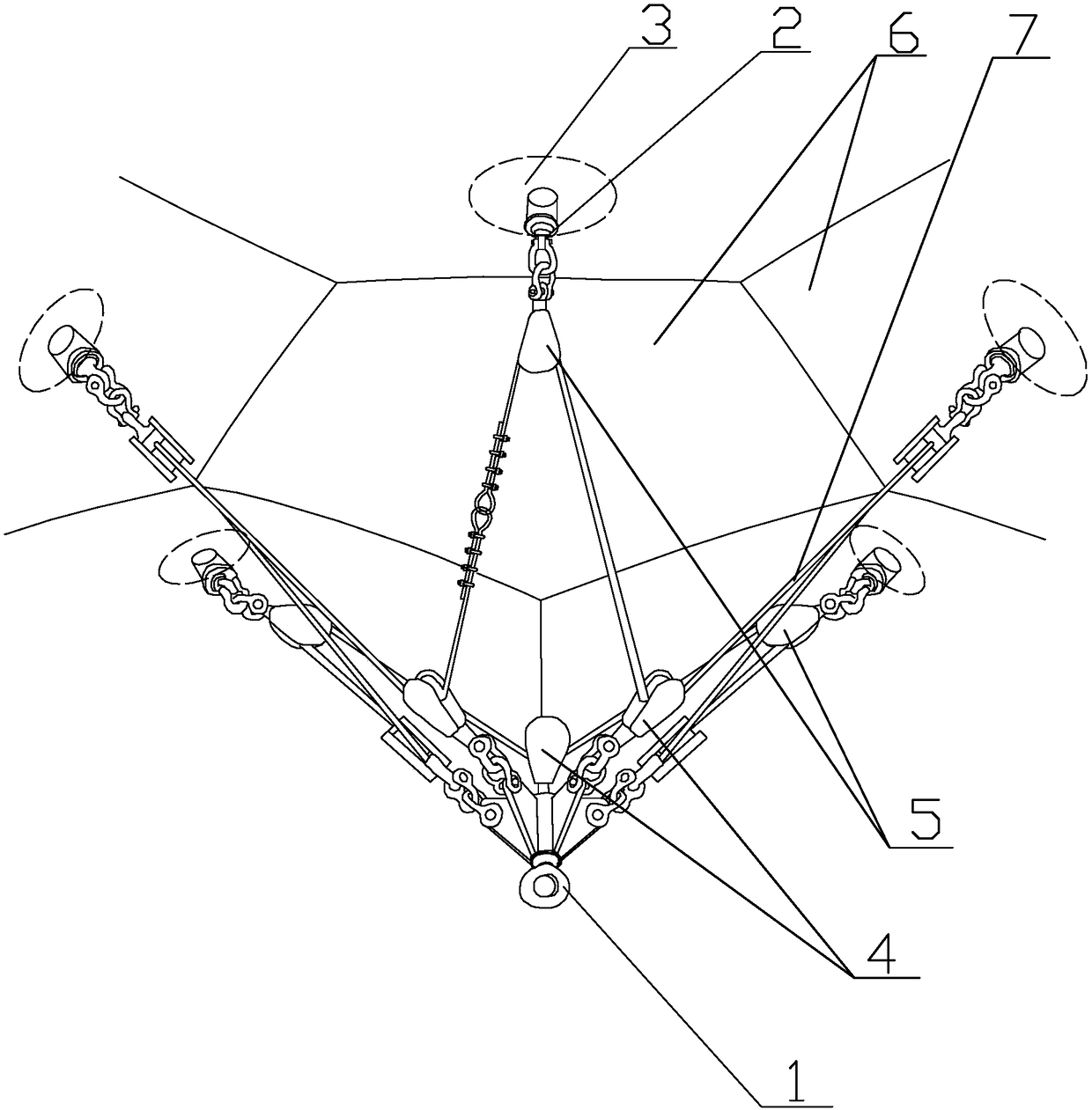
[0035] Specific implementation mode one: combine Figure 1-Figure 12 Describe this embodiment, a radome top sling device, it has a main suspension point assembly (1), N auxiliary suspension point assemblies (2), N fixed pulley assemblies (5), N movable pulley assemblies ( 4) and the steel wire rope (7), N auxiliary lifting point assemblies (2) are used to be installed on the top of the radome, and the centers of the N auxiliary lifting point assemblies (2) are on the same horizontal plane and on the same circumference, The N fixed pulley assemblies (5) are installed on the N auxiliary lifting point assemblies (2) one by one, the N fixed pulley assemblies (5) are located above the N movable pulley assemblies (4), and the N movable pulley assemblies ( 4) Evenly distributed around a main lifting point assembly (1), a fixed pulley assembly (5) is arranged above every two movable pulley assemblies (4), and the head end of the wire rope (7) passes through A movable pulley assembly ...
specific Embodiment approach 2
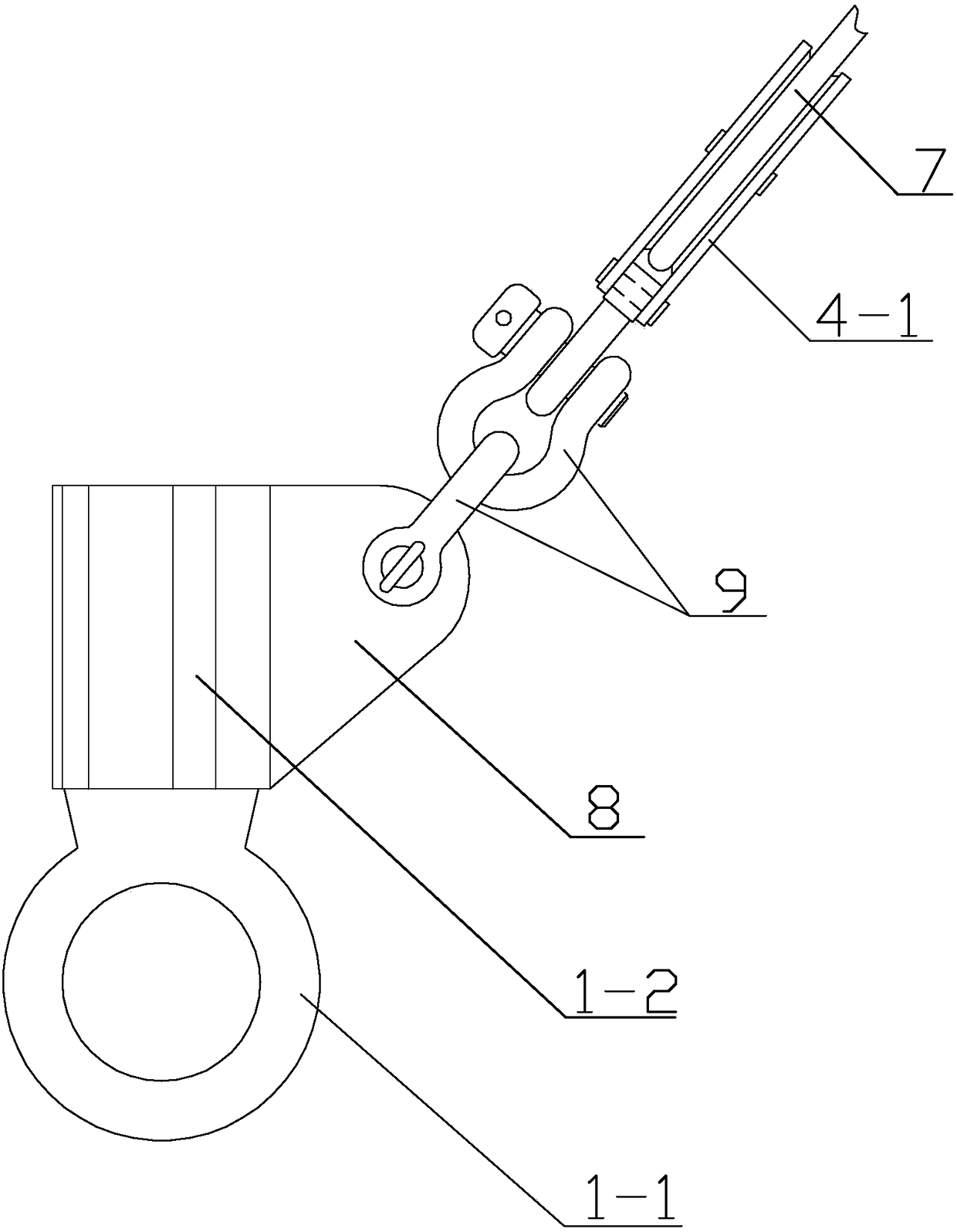
[0036] Specific implementation mode two: combination figure 1 , figure 2 , Figure 4 with Figure 5 To illustrate this embodiment, the main lifting point assembly 1 includes a main lifting point connecting shaft 1-2, N hanging wings 8 and a lifting ring 1-1, and the lower end of the main lifting point connecting shaft 1-2 is equipped with a lifting ring 1-1. The hanging point connecting shaft 1-2 is processed into a spline shaft, and the suspension wings 8 are installed in the groove of the spline shaft. The arc end of each suspension wing 8 is processed with a through hole, and the through hole of the suspension wing 8 passes through the bolt and the movable pulley. Assembly 4 is hinged. The beneficial effects of this embodiment: the suspension wing 8 is connected to the main suspension point shaft 1-2 by welding, which ensures the structural strength of the main suspension point assembly 1 and the safety of the main suspension point assembly 1, except Except that the ha...
specific Embodiment approach 3
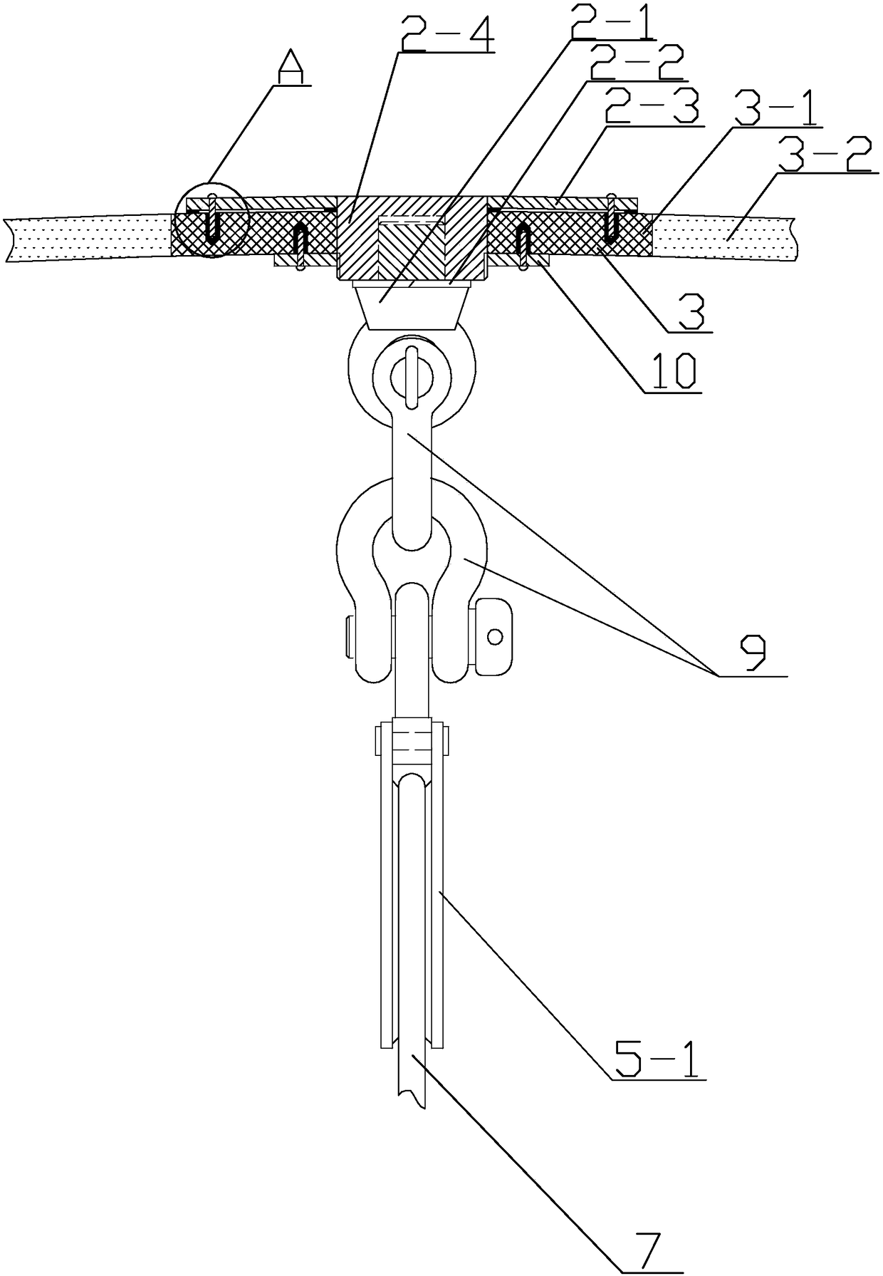
[0037] Specific implementation mode three: combination figure 1 , image 3 , Figure 7 with Figure 8 To illustrate this embodiment, N auxiliary lifting point assemblies 2 include auxiliary lifting point connecting shaft 2-4, eyebolt 2-1, auxiliary lifting point end cover 2-3 and spring washer 2-2, auxiliary lifting point connecting shaft 2 Threads are processed on the outer wall of the lower part of -4, holes are processed on both sides of the auxiliary lifting point end cover 2-3, the auxiliary lifting point end cover 2-3 is welded on the upper part of the auxiliary lifting point connecting shaft 2-4, the auxiliary lifting point The upper end surface of the connecting shaft 2-4 is on the same level as the upper end surface of the auxiliary lifting point end cover 2-3, the auxiliary lifting point connecting shaft 2-4 is also processed with internal thread holes, and the upper part of the lifting eye bolt 2-1 is processed with threads, The spring washer 2-2 is arranged at t...
PUM
| Property | Measurement | Unit |
|---|---|---|
| Diameter | aaaaa | aaaaa |
| Nominal diameter | aaaaa | aaaaa |
Abstract
Description
Claims
Application Information
 - R&D
- Intellectual Property
- Life Sciences
- Materials
- Tech Scout
- Unparalleled Data Quality
- Higher Quality Content
- 60% Fewer Hallucinations
Browse by: Latest US Patents, China's latest patents, Technical Efficacy Thesaurus, Application Domain, Technology Topic, Popular Technical Reports.
© 2025 PatSnap. All rights reserved.Legal|Privacy policy|Modern Slavery Act Transparency Statement|Sitemap|About US| Contact US: help@patsnap.com