Construction method for shear wall setting steel framework bracing unidirectional fastening screw on deformation joint

A technology for tightening screws and construction methods, applied in the processing of building materials, construction, building structure, etc., can solve the problem that the flatness, verticality, concrete compactness, and shear wall formwork at deformation joints of shear walls cannot be guaranteed. The problems of inconvenient support method and unsatisfactory quality of shear wall at deformation joints have achieved the effect of safe and reliable engineering quality, simple structure and reduced engineering cost.

Inactive Publication Date: 2018-08-10
MCC5 GROUP CORP SHANGHAI
View PDF5 Cites 10 Cited by
  • Summary
  • Abstract
  • Description
  • Claims
  • Application Information

AI Technical Summary

Problems solved by technology

[0002] It is more difficult to support the shear wall formwork at the deformation joint, and it is more difficult to remove the formwork, which may easily cause the shear wall formwork to remain in the deformation joint
The traditional support method of the shear wall formwork at the deformation joints is to use filled extruded panels and use waste formwork to make the box shell, but the quality of the shear wall at the deformation joints is not satisfactory, and the smoothness of the shear wall cannot be guaranteed. Degree, verticality and concrete compactness
[0003] Therefore, there are above-mentioned inconveniences and problems in the support mode of the shear wall formwork at the known deformation joints.

Method used


Image

  • Construction method for shear wall setting steel framework bracing unidirectional fastening screw on deformation joint
  • Construction method for shear wall setting steel framework bracing unidirectional fastening screw on deformation joint

Examples


Embodiment 1

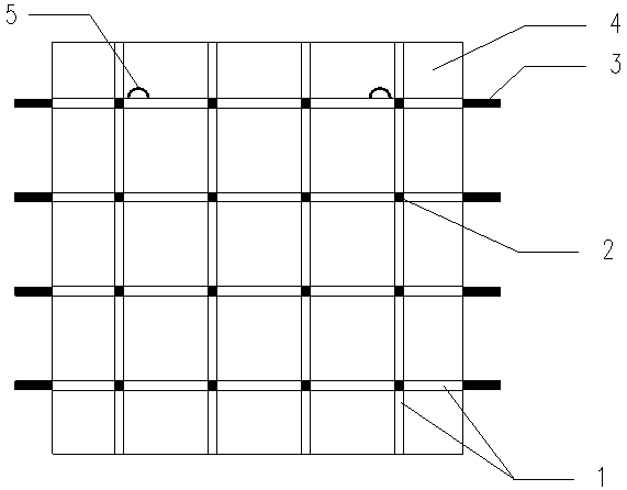
[0033] The technical process of the construction method of the shear wall shaped steel formwork supporting the one-way fastening screw at the deformation joint of the present invention: template making (shear wall shaping steel mold making, wooden mold making) → vertical steel bar binding → steel bar acceptance → formwork assembly Positioning (the wooden formwork is in place first, and then the steel formwork is in place) → formwork reinforcement (penetrate the tension screw to reinforce the wooden formwork and steel formwork) → formwork acceptance → concrete pouring.

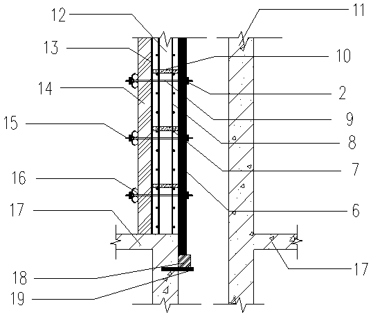
[0034] According to the construction method of the present invention for supporting the shaped steel formwork of the shear wall at the deformation joint, the shear walls on both sides of the deformation joint are based on the poured floor slabs of the same height, and the shear wall 11 on one side has been poured. The other side of the shear wall 12 to be poured is provided with a one-way fastening screw, and th...


PUM


Abstract

The invention discloses a construction method for a shear wall setting steel framework bracing unidirectional fastening screw on a deformation joint. The construction method is characterized in comprising the following steps: a, according to a drawing, carrying out template sample refurbishment, and manufacturing a setting steel framework and a wood pattern used for a shear wall on the deformationjoint; b, after the vertical reinforcing steel bars of the shear wall finish binding acceptance check, installing a template; c, mutually contrasting an inner side timber formwork and an outer side steel framework to enable a split bolt to be penetrated; d, after the framework finishes being reinforced, carrying out framework acceptance check; e, pouring concrete. The construction method for theshear wall setting steel framework bracing unidirectional fastening screw on the deformation joint has the advantages of simple structure of the shear wall setting steel framework bracing device, convenience in manufacture and safe and reliable engineering quality, the integral rigidity of the shear wall framework on the deformation joint can be improved, the flatness and the perpendicularity of the shear wall framework on the deformation joint are guaranteed, the compactness of the concrete is guaranteed, engineering cost is lowered, concrete forming quality is guaranteed, and the functions of lowering cost and increasing effects are performed.

Description

technical field [0001] The invention relates to a method for supporting post-cast shear wall templates at deformation joints, in particular to a construction method for supporting one-way fastening screw rods for shear wall shaped steel templates at deformation joints. Background technique [0002] It is more difficult to support the shear wall formwork at the deformation joint, and it is more difficult to remove the formwork, which may easily cause the shear wall formwork to remain in the deformation joint. The traditional method of supporting the formwork of the shear wall at the deformation joint is to use filled extruded panels and use waste formwork to make the box shell, but the quality of the shear wall at the deformation joint is not satisfactory, and the smoothness of the shear wall cannot be guaranteed. degree, verticality and concrete compactness. [0003] Therefore, there are above-mentioned inconveniences and problems in the supporting mode of the shear wall fo...

Claims


Application Information

Patent Timeline
Patent Type & Authority Applications(China)
IPC IPC(8): E04G21/00
Inventor 杨超
Owner MCC5 GROUP CORP SHANGHAI
Why Eureka
Try Eureka