
Underground in-situ multi-parameter anisotropy detection device for rock

A measuring device and anisotropy technology, which is applied in the field of oil and gas experiments, can solve the problems of inability to accurately test multi-parameter anisotropy of rocks at the same time, and achieve the effects of uniform force, end face sealing, and fast and accurate temperature control

Active Publication Date: 2018-08-10
CHENGDU UNIVERSITY OF TECHNOLOGY
View PDF11 Cites 9 Cited by
  • Summary
  • Abstract
  • Description
  • Claims
  • Application Information

AI Technical Summary

Problems solved by technology

[0004] The purpose of the present invention is to provide a measuring device that can simultaneously measure permeability, strain, sound wave and resistance anisotropy while keeping the in-situ temperature and true triaxial stress of the rock in the ground constant, so as to solve the problem that existing devices cannot Drawbacks of accurate and simultaneous testing of multi-parameter anisotropy of rocks in subsurface in-situ temperature-stress environments

Method used


Image

  • Underground in-situ multi-parameter anisotropy detection device for rock
  • Underground in-situ multi-parameter anisotropy detection device for rock
  • Underground in-situ multi-parameter anisotropy detection device for rock

Examples


Embodiment Construction

[0016] The specific implementation manner of the present invention will be further described in detail below in conjunction with the accompanying drawings and specific examples.

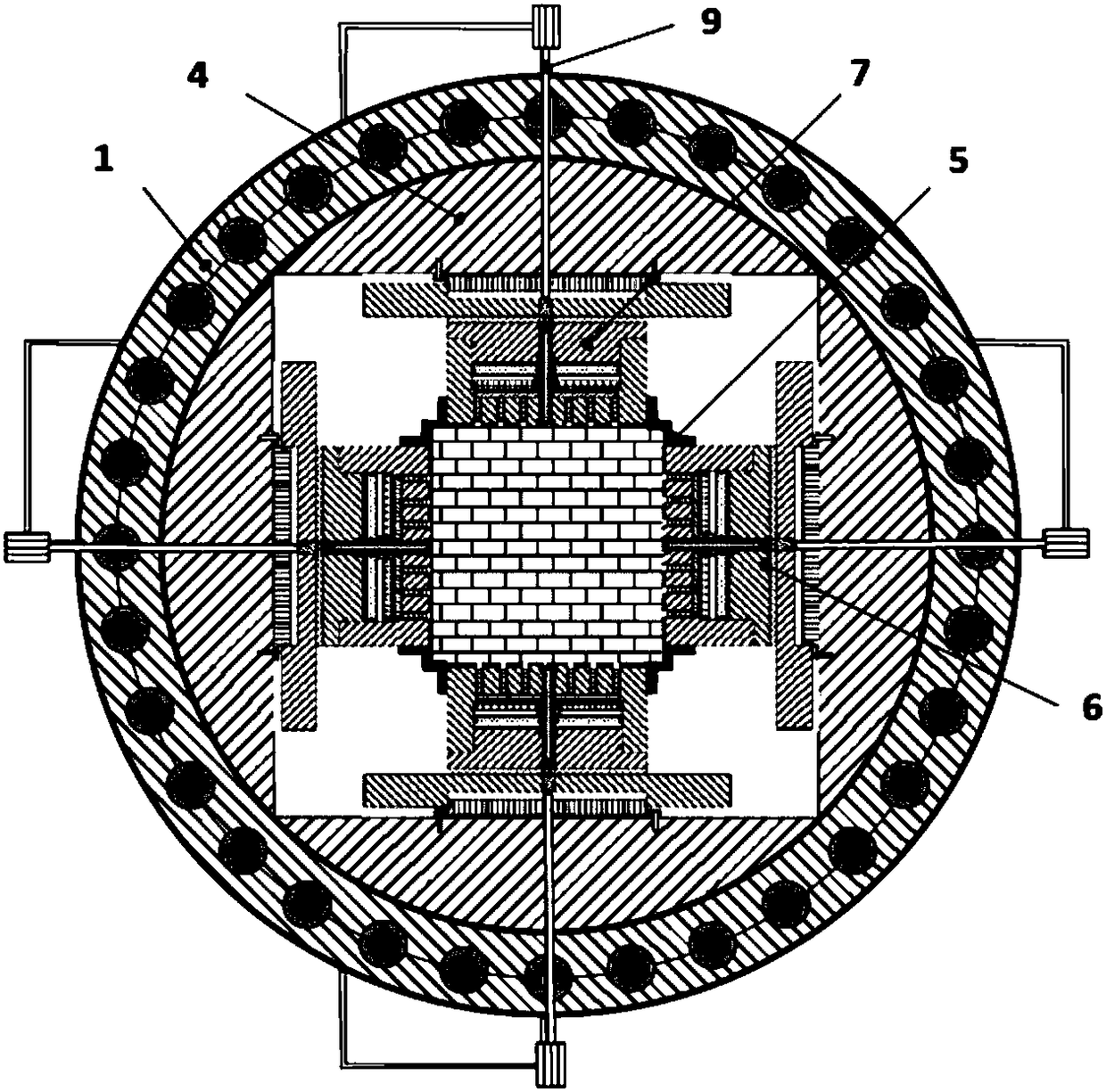
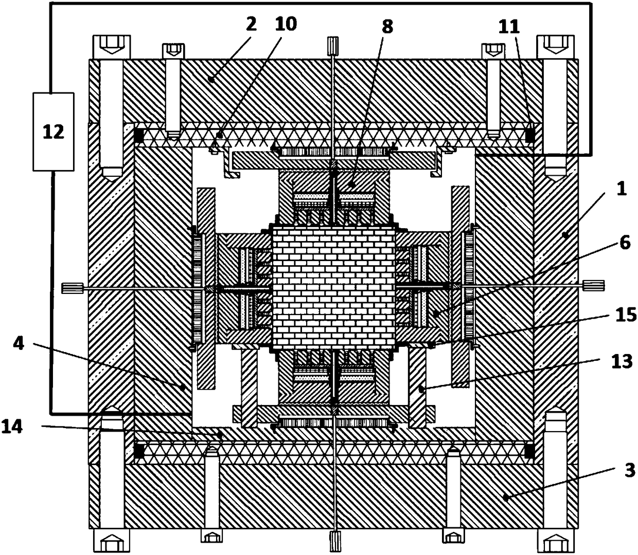
[0017] Such as Figure 1~2 As shown, an in-situ multi-parameter anisotropy measuring device for underground rocks, including a pressure-bearing cylinder 1, an upper flange 2, a lower flange 3, an arc-shaped vertical plate 4, a frame-type rubber sleeve 5, and an X-direction combined hydraulic pressure Cylinder 6, Y direction combined hydraulic cylinder 7, Z direction combined hydraulic cylinder 8, deformation sensor 9, cavity plug 10, sealing ring 11, cycle pressurization temperature control system 12, support rod 13, support base plate 14 and support gasket 15. The measuring device is composed of a pressure-bearing cylinder and an upper flange and a lower flange bolted on the upper and lower sides of the pressure-bearing cylinder. The square core is placed in a frame-type rubber sleeve and placed in ...


PUM


Abstract

An underground in-situ multi-parameter anisotropy detection device for a rock includes a pressure cylinder body, an upper flange, a lower flange, arc-shaped vertical plates, a frame rubber sleeve, anX-direction combined hydraulic cylinder, a Y-direction combined hydraulic cylinder, a Z-direction combined hydraulic cylinder, a deformation sensor, cavity plugs, a sealing ring, a circulating pressurized temperature control system, support rods, a support bottom plate and support gaskets, the device is composed of the pressure cylinder body, the upper flange and the lower flange, a rock core is placed in the frame rubber sleeve, the three-axis direction combined hydraulic cylinders respectively act on the rock core, the X-direction combined hydraulic cylinder and the Y-direction combined hydraulic cylinder are fixed on the pressure cylinder by the arc-shaped vertical plates, the Z-direction combined hydraulic cylinder is fixed at two ends of the pressure cylinder body via the cavity plugsand the flanges, the deformation sensor is arranged at the center of the combined hydraulic cylinders, the sealing ring is arranged between the cavity plugs and the pressure cylinder body, the support bottom plate is arranged between the lower part of the Z-direction combined hydraulic cylinder and the cavity plugs, the support gaskets are arranged at the bottoms of the X-direction combined hydraulic cylinder and the Y-direction combined hydraulic cylinder, one ends of the support rods are fixed on the support bottom plate, and the other ends of the support rods are mounted on the support gaskets to support the weights of the X-direction combined hydraulic cylinder and the Y-direction combined hydraulic cylinder.

Description

technical field [0001] The invention belongs to the technical field of oil and gas experiments, and relates to a testing device for multi-parameter anisotropy of rocks under real underground temperature and stress environments, in particular to a method for simultaneously measuring permeability, True Triaxial Gripper for Strain, Acoustic, Resistance Anisotropy. Background technique [0002] Oil and gas reservoir rocks are affected by their own deposition, diagenesis, and underground heterogeneous stress environment, and their in-situ permeability, strain, acoustic wave, electrical resistance and other parameters often show obvious heterogeneity and anisotropy. Accurate evaluation of the in-situ anisotropy characteristics of various parameters of oil and gas reservoir rocks is of great significance to the development of oil and gas fields. split plan, etc. [0003] The traditional rock physical anisotropy test device can not accurately reflect the stress state of the rock i...

Claims


Application Information

Patent Timeline
Patent Type & Authority Applications(China)
IPC IPC(8): G01N15/08G01N27/04G01N3/18G01N29/04G01N33/24G01D21/02
CPCG01D21/02G01N3/18G01N15/082G01N27/041G01N29/04G01N33/24G01N2203/0019G01N2203/0048G01N2203/0222G01N2203/0244G01N2203/0256G01N2203/0682
Inventor 郑军孙振介王可可刘鸿博
Owner CHENGDU UNIVERSITY OF TECHNOLOGY
Learn More