An experimental device and method for recording detonation cell structure

An experimental device and cell technology, applied in the field of detonation testing, can solve the problems of poor heat resistance, damaged film, impact, etc., and achieve the effect of good heat resistance, good strength and flexibility

Active Publication Date: 2019-01-29
XI AN JIAOTONG UNIV
View PDF7 Cites 0 Cited by
  • Summary
  • Abstract
  • Description
  • Claims
  • Application Information

AI Technical Summary

Problems solved by technology

Second, it is difficult to ensure the tightness of the pipeline by opening large-area windows, and the loading and unloading process is also time-consuming
But polyester film also has two fatal shortcomings
One is that the strength is poor, there is a small gap between the film and the tube wall, and the detonation wave can destructively destroy the film, and the success of the experiment is extremely low
Moreover, the film fragments produced have certain viscosity under the high temperature of the detonation, and are easy to adhere to the inside of the detonation tube or even the test instrument, which will have a negative impact on the subsequent detonation experiment.
The second is that the heat resistance is poor, and it is more time-consuming and laborious in the process of soot smoking. The high temperature of the detonation flame will also cause embrittlement of the film, which will affect the measurement and shooting of the detonation cell size.

Method used


Image

  • An experimental device and method for recording detonation cell structure
  • An experimental device and method for recording detonation cell structure
  • An experimental device and method for recording detonation cell structure

Examples


Embodiment Construction

[0019] Below in conjunction with accompanying drawing and specific embodiment the present invention is described in detail:

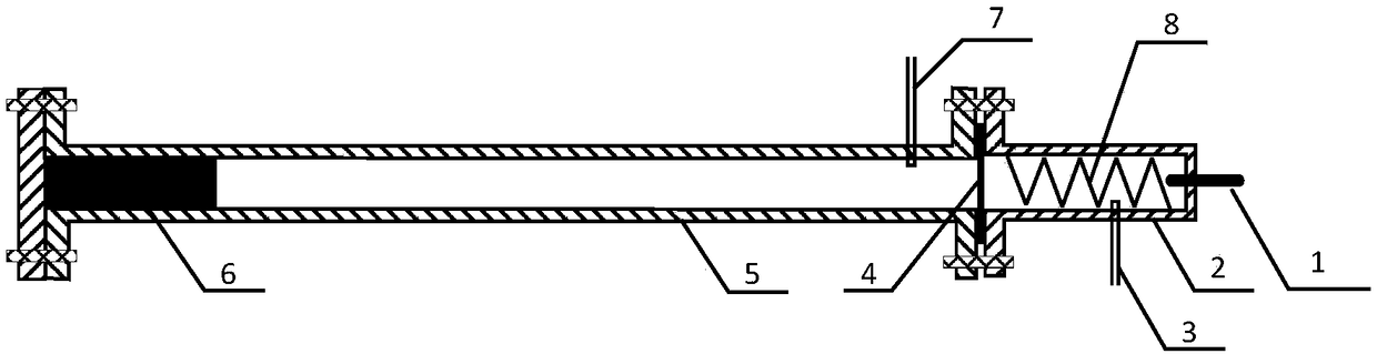
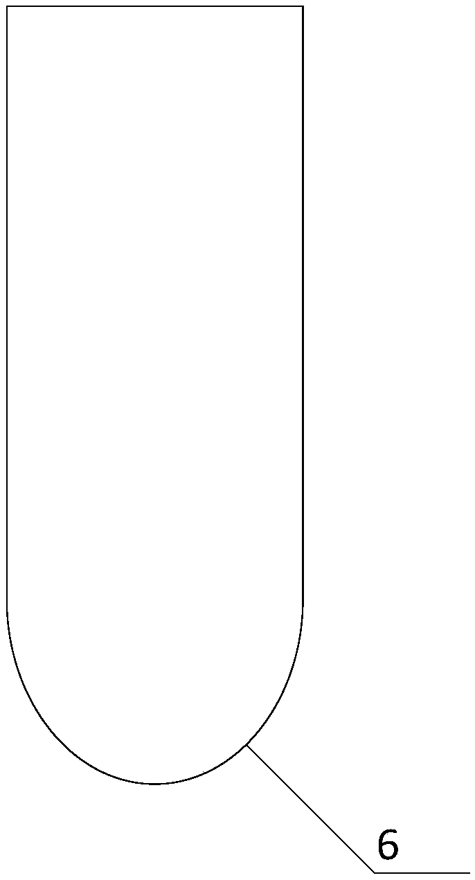
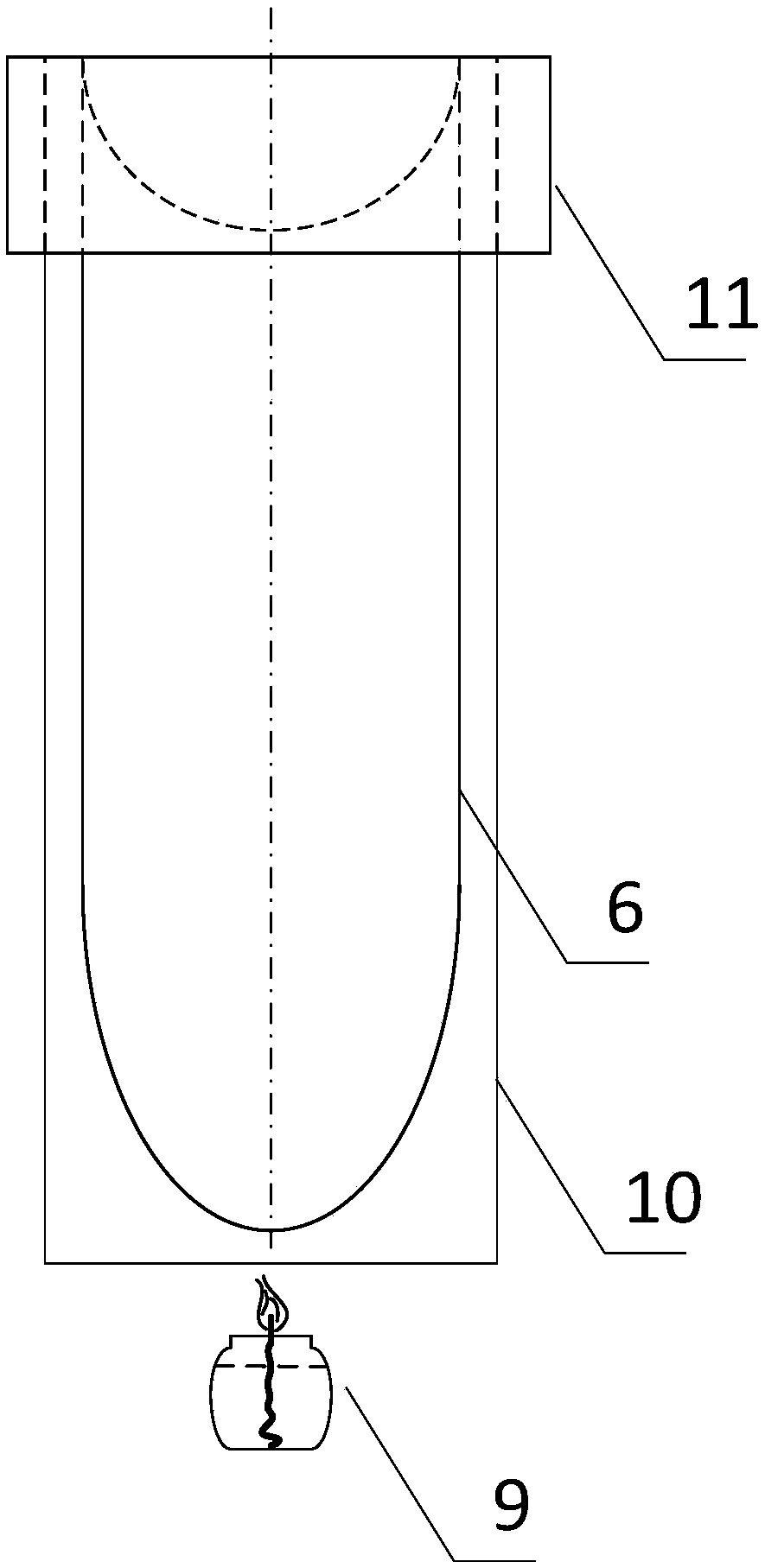
[0020] Such as figure 1 As shown, the present invention is an experimental device for recording detonation cell structure. The main section of the experiment is a detonation tube 5. The front end of the detonation tube 5 is connected to the driving section 2. The flame disturbs the spiral structure 8 so as to accelerate the flame; since the gas filled in the detonation tube 5 and the driving section 2 are different, the diaphragm 4 is used for isolation; The intake pipe 7 and the intake pipe 3 of the detonation section of acetylene; the smoked aluminum plate 6 formed by rolling is arranged in the end of the detonation tube 5, the smoked aluminum plate 6 is closely attached to the tube wall of the detonation tube 5, and the smoked aluminum plate 6 The width is 10-30mm smaller than the circumference of the detonation tube 5, and the winding gap is placed...


PUM

PropertyMeasurementUnit
thicknessaaaaaaaaaa
lengthaaaaaaaaaa
lengthaaaaaaaaaa

Abstract

The invention discloses an experimental device for recording a detonation cell structure, and a method thereof. The experimental device comprises an ignition bar, a driving segment, a detonation tube,a diaphragm, a flame disturbing spiral and an air inlet. The cell structure is recorded by using a smoke foil technique, a mirror aluminum plate having the advantages of good flexibility, good high temperature resistance and good strength is used as a smoked surface, and the front end of the aluminum plate is trimmed to form an arc shape in order to ensure that the aluminum plate is destroyed inthe detonation process; when smoking is performed, the aluminum plate is first rolled to form a semi-cylindrical shape, then is sealed with a flat plate, and is smoked by a kerosene lamp; the smokingtime of every end of the aluminum plate is controlled to about 5 min in order to obtain the clear cell structure in order to avoid excessive thickness of a smoke film; and after a detonation experiment is performed, condensed water is attached to the surface of the aluminum plate, and the aluminum plate is immediately dried by a hot air blower to prevent liquid drops generated in natural air drying from eroding the cell structure. The clear cell structure is obtained by the low-cost method, so the measurement of the size of the cell is accurate, and reliable experimental data is provided for further completing and developing the theory research of gaseous detonation.

Description

technical field [0001] The invention relates to the technical field of detonation testing, in particular to an experimental device and method for recording gas-phase detonation cell structure. Background technique [0002] When a serious accident occurs in a pressurized water reactor nuclear power plant, the zirconium cladding of the reactor core is oxidized by steam or air to produce a large amount of hydrogen. In addition, if the core melt falls into the reactor cavity, the interaction between the melt and concrete will produce a large amount of hydrogen or carbon monoxide. Mixing these gases with the surrounding air and steam may create a flammable mixture that will burn slowly when exposed to an electric spark or heat source. However, the combustion flame is extremely unstable. If there is an obstacle in the propagation path of the flame, the turbulence caused will increase the combustion rate and accelerate the propagation of the flame. Under the right conditions, thi...

Claims


Application Information

Patent Timeline
Patent Type & Authority Patents(China)
IPC IPC(8): G01N25/54G01N1/28
CPCG01N1/28G01N25/54
Inventor 苏光辉陈勇征刘博张亚培田文喜秋穗正
Owner XI AN JIAOTONG UNIV
Why Eureka
Try Eureka