Cable bridge end structure and construction method for cable bridge to pass through fire compartment

A cable tray and construction method technology, applied in the direction of electrical components, etc., can solve problems such as inability to install, unattractive visual effects, and difficulty in filling and blocking completely with fireproof materials

Inactive Publication Date: 2018-08-10
CHINA 22MCC GROUP CORP
View PDF4 Cites 0 Cited by
  • Summary
  • Abstract
  • Description
  • Claims
  • Application Information

AI Technical Summary

Problems solved by technology

The disadvantages of this are as follows: 1. The fireproof material is not easy to fill completely, because the connection between the cable bridge and the steel pipe is inconvenient for construction and operation; Small but more steel pipes are reserved); 3. The traditional method of bridge cover is not easy or impossible to install, and the visual effect is not very beautiful

Method used


Image

  • Cable bridge end structure and construction method for cable bridge to pass through fire compartment
  • Cable bridge end structure and construction method for cable bridge to pass through fire compartment
  • Cable bridge end structure and construction method for cable bridge to pass through fire compartment

Examples


Embodiment Construction

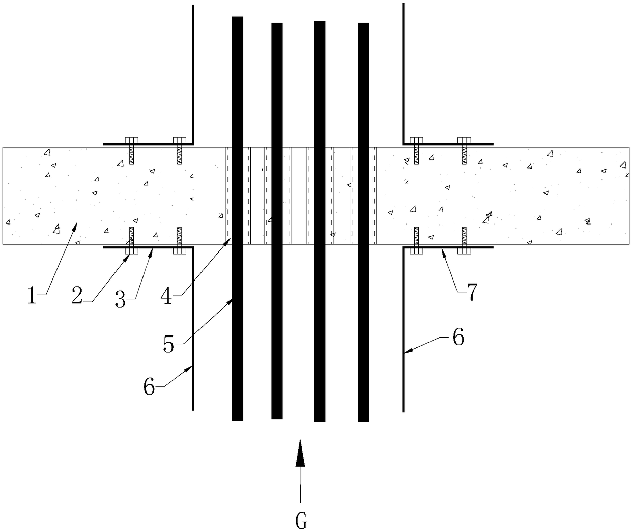
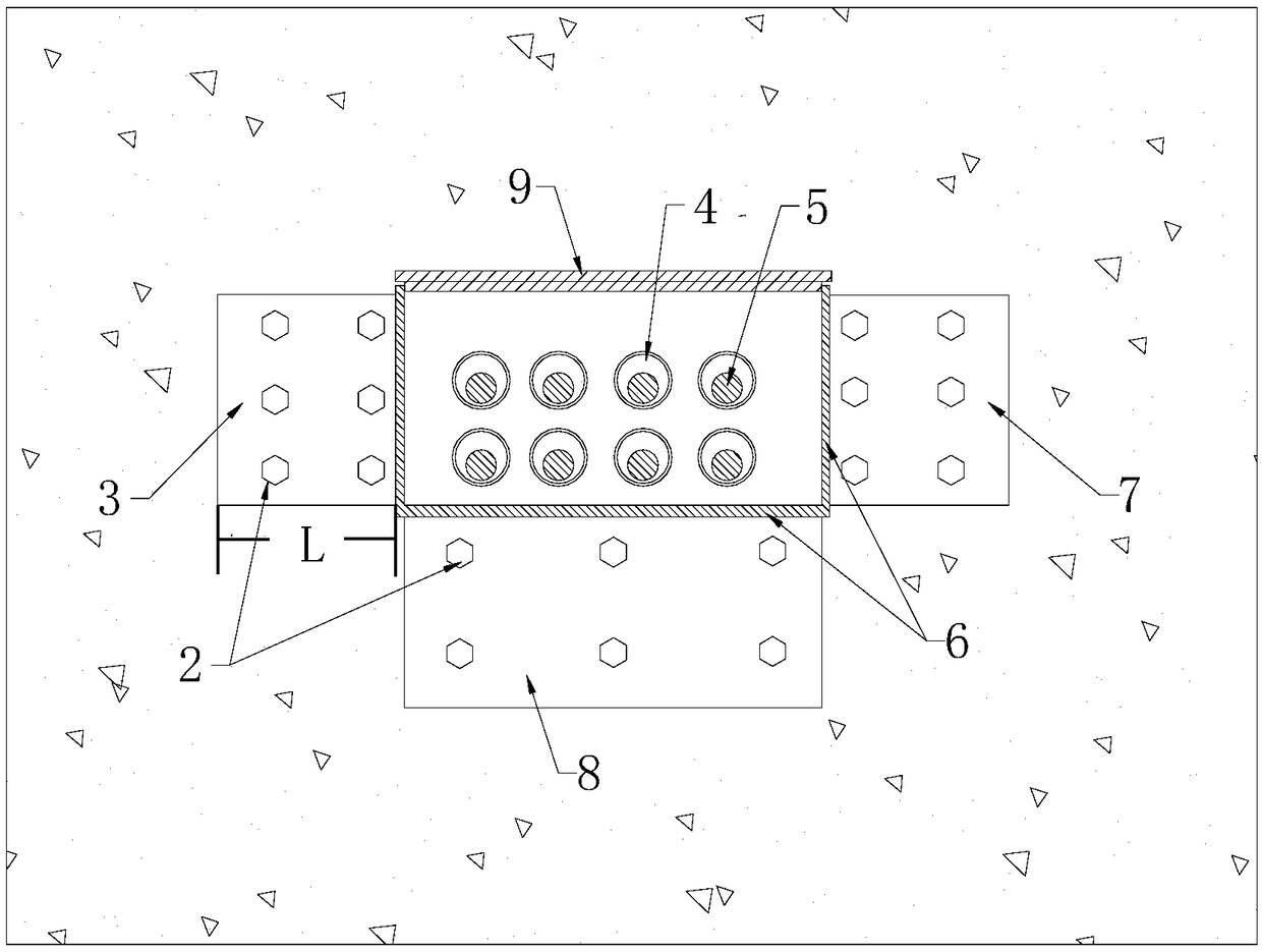
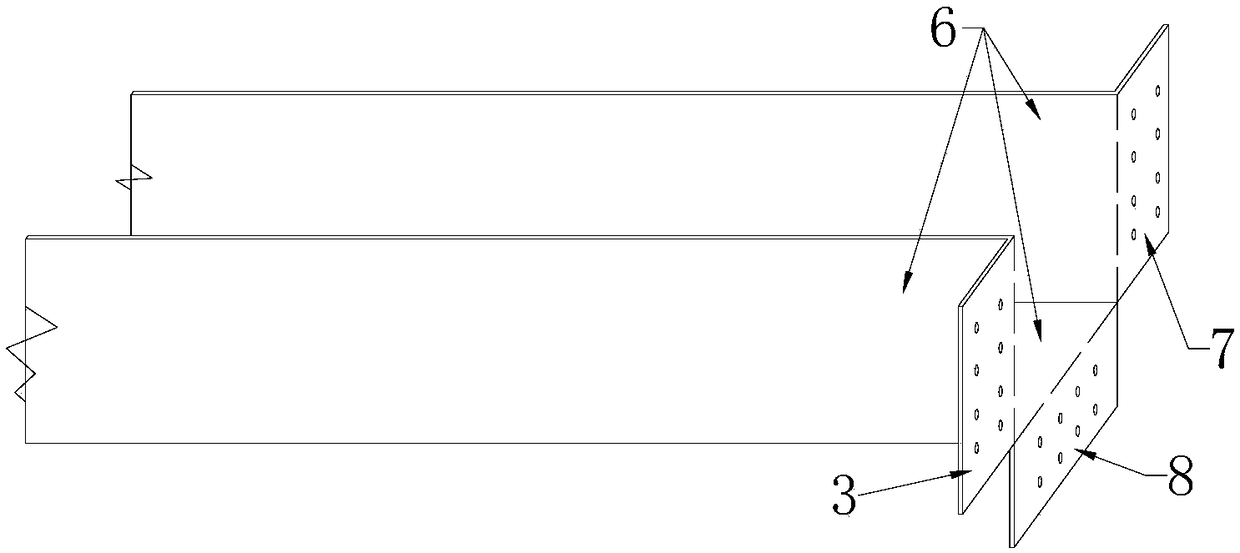
[0025] Below the present invention is described in detail: as Figure 1-5 The cable tray shown in the above includes a concave-shaped bridge frame made of three baffles 6, and the design structure of the connecting end is improved, specifically: the ends of the baffles 6 on the three sides of the bridge are provided with valgus ends, and the valgus The ends form the left end face 3, the right end face 7, the lower end face 8 with respect to the angle of 90 degrees of the respective main faces, and the left end face 3, the right end face 7, the lower end face 8 are respectively provided with some installation holes.

[0026] In the original construction method, the end of the bridge frame is directly against the wall 1, the port is set on the embedded steel pipe 4, and then the contact points are fixed and sealed. The construction is to coat the inner and outer sides of the bridge frame respectively. Sufficient quantity of fireproofing material10. But because the bridge frame ...


PUM


Abstract

The invention provides a cable bridge end structure, and the structure comprises a bridge with three baffle plates. The end parts of the baffle plates are each provided with an everted end, and the everted ends form 90-degree bent left end face, right end face and lower end face, wherein three end faces are respectively provided with a plurality of installation holes. The invention also provides aconstruction method for a cable bridge to pass through a fire compartment, and the method comprises the steps: 1, separating the welding points of the three baffle plates of a cable bridge end by a certain length L; 2, enabling the separated ends to be everted by 90 degrees, and forming the left end face, the right end face and the lower end face; 3, sleeving a wall pre-buried steel pipe part through a bridge, enabling the left end face, the right end face and the lower end face to be attached to the surface of a wall, and fixing the left end face, the right end face and the lower end face through steel nails; 4, carrying out the filling of a fireproof material and the end blocking after the arrangement of the cable; 5, performing the covering through a bridge cover plate. The method greatly enlarges the contact area of the cable bridge and the wall, does not need to carry out the filling of the fireproof material at the inner sides of the baffle plates, is quick in construction, is large in contact area, and is good in fireproof and sealing effect. Moreover, the appearance is regular, neat and beautiful.

Description

technical field [0001] The invention relates to the technical field of building electrical construction, in particular to a construction method for an end structure of a cable bridge and a cable bridge passing through a fire compartment. Background technique [0002] At present, according to the "Air Defense Law of the People's Republic of China", new civil buildings in cities must build basements that can be used for air defense during wartime in accordance with relevant national regulations, which involves the situation where cable bridges pass through fire compartments. According to the requirements of building codes, cable trays cannot directly pass through fire compartments. At the same time, page 61 of 05SFD10 Atlas 5-5 introduces how cable trays pass through fire compartments. However, the atlas does not specify how the bridge frame is connected to the steel pipes. The traditional method is to directly cover the steel pipe with the cable bridge, and then block it wit...

Claims


Application Information

Patent Timeline
Patent Type & Authority Applications(China)
IPC IPC(8): H02G3/04
CPCH02G3/0406
Inventor 袁盼杨培明高菲王丽娜
Owner CHINA 22MCC GROUP CORP
Why Eureka
Try Eureka