
anchor fracture fixation device

A fixation device and anchor-like technology, which is applied in the field of medical devices, can solve the problems of inconvenient operation and complications of the fixation device, and achieve the effects of avoiding foreign body rejection, reducing burden and reducing workload

Active Publication Date: 2020-05-01
宋鹏
View PDF14 Cites 0 Cited by
  • Summary
  • Abstract
  • Description
  • Claims
  • Application Information

AI Technical Summary

Problems solved by technology

[0004] In view of the above situation, in order to overcome the defects of the prior art, the object of the present invention is to provide an anchor fracture fixation device, which effectively solves the problems of inconvenient operation of the fixation device and complications after treatment.

Method used


Image

  • anchor fracture fixation device
  • anchor fracture fixation device
  • anchor fracture fixation device

Examples


Embodiment Construction

[0010] The following is attached Figure 1-3 The specific implementation manner of the present invention will be described in further detail.

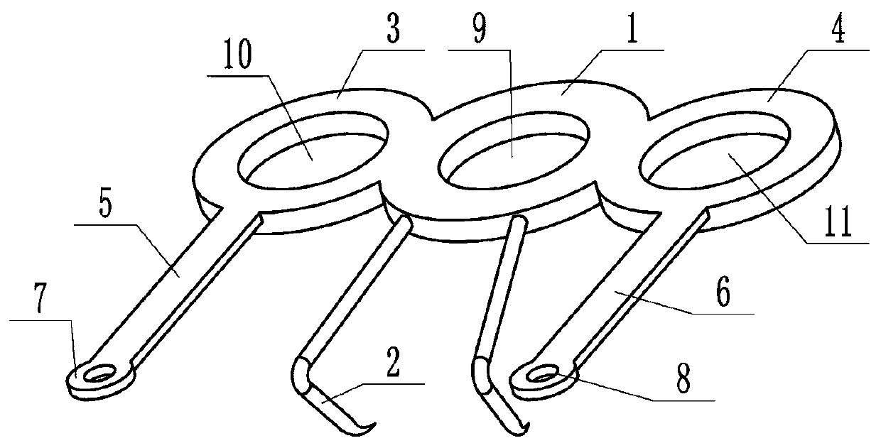
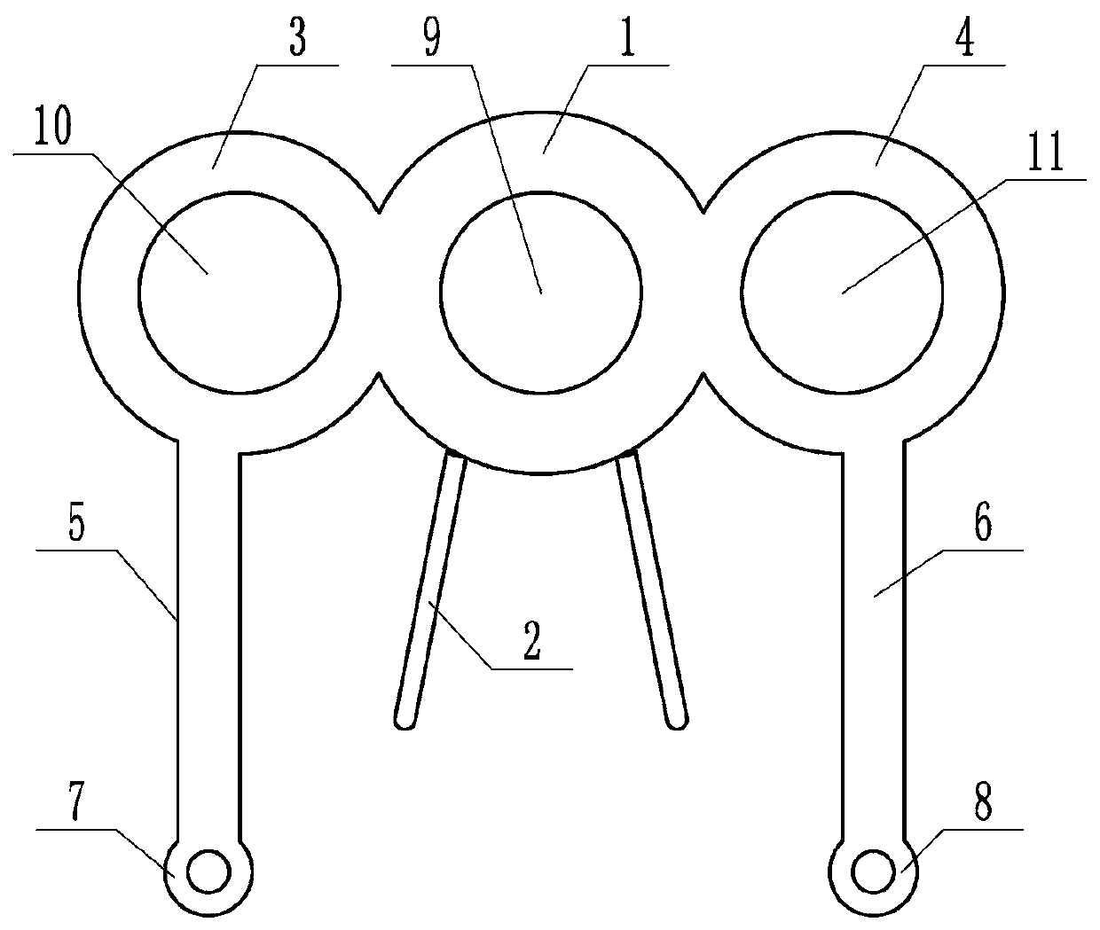
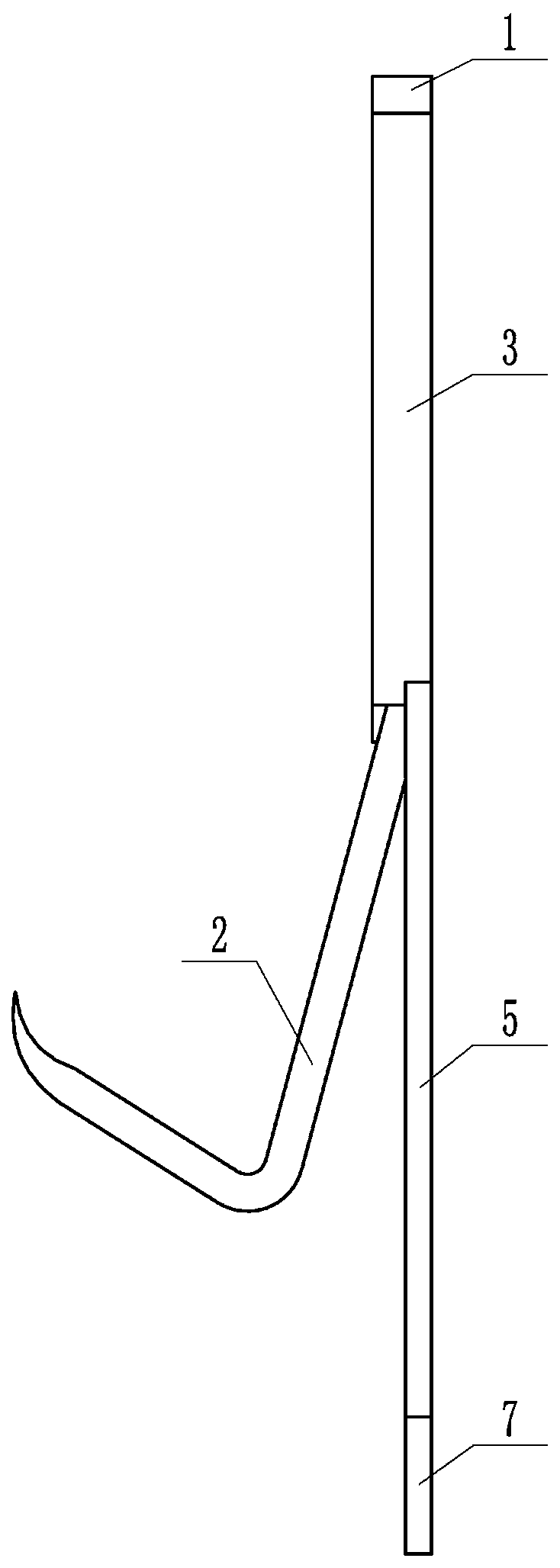
[0011] Depend on Figure 1 to Figure 3 It can be seen that an anchor fracture fixation device of the present invention includes a central anchor ring 1, and two anchor hooks 2 extending obliquely from the same side of the central anchor ring 1 have two anchor hooks 2 in different directions. Ring 1 is in the first anchor ring 3 and the second anchor ring 4 on the same horizontal plane, and the first anchor ring 3 protrudes from the first anchor rod 5 on the same side as the anchor hook 2, and the second anchor ring 4 protrudes from the outside. For the second anchor rod 6 on the same side as the anchor hook 2 , a first anchor rod ring 7 is provided at the end of the first anchor rod 5 , and a second anchor rod ring 8 is provided at the end of the second anchor rod 6 .

[0012] The central anchor ring 1, the first anchor ring 3 and th...


PUM


Abstract

An anchor-shaped bone fracture fixing device effectively solves the problems that a fixing device is not convenient to operate and complications exist after treatment. By means of the technical schemefor solving the technical problems, the anchor-shaped bone fracture fixing device comprises a central anchor ring. Two anchor hooks in different directions extend out of the same side of the centralanchor ring obliquely. The two sides of the central anchor ring are symmetrically connected with a first anchor ring and a second anchor ring which are located on the same horizontal plane as the central anchor ring. A first anchor rod located on the same side as the corresponding anchor hook extends out of the first anchor ring. A second anchor rod located on the same side as the corresponding anchor hook extends out of the second anchor ring. A first anchor rod ring is arranged at one end of the first anchor rod, and a second anchor rod ring is arranged at one end of the second anchor rod.

Description

technical field [0001] The invention relates to the technical field of medical instruments, in particular to an anchor fracture fixation device. Background technique [0002] Mallet Finger is a deformity in which the extensor tendon of the finger is ruptured at the insertion point, and the distal segment cannot be straightened. Classification of mallet finger deformity: one is bony deformity: the avulsion fracture at the insertion point of the extensor tendon of the distal finger; the other is tendinous deformity, that is, the rupture of the extensor tendon at the insertion point. It is often caused by a small external force, such as opening the door or playing basketball: because the end of the finger is stretched under the action of the extensor contraction when holding the object, and is collided by a sudden external force, causing the end of the finger to flex strongly, flexion and straightening The force causes the extensor tendon terminal insertion to rupture, and oft...

Claims


Application Information

Patent Timeline
Patent Type & Authority Patents(China)
IPC IPC(8): A61B17/68
CPCA61B17/683
Inventor 宋鹏
Owner 宋鹏
Learn More