
Wire control arm and robot

An arm, wire-controlled technology, applied in the direction of program control manipulators, manipulators, joints, etc., can solve the problems of increasing arm weight, lack of flexibility, motor component weight, volume and inertia, etc., to reduce driving torque, reduce arm The effect of weight

Inactive Publication Date: 2018-08-14
NINGBO GQY VIDEO &TELECOM
View PDF6 Cites 1 Cited by
  • Summary
  • Abstract
  • Description
  • Claims
  • Application Information

AI Technical Summary

Problems solved by technology

[0003] However, the arm joints of existing robots are often driven by a driving mechanism formed by a combination of motor acceleration and reducer installed at the arm, which makes the cost of the robot high, and because the driving mechanism is installed at the arm, the weight of the arm is increased, making the arm The driving torque is limited, and the gears are prone to be damaged by external forces; and due to the shortcomings of the weight, volume and inertia of the motor components, the robot's movement speed cannot be increased, the degree of freedom is small, and it does not have the disadvantages of flexibility.

Method used

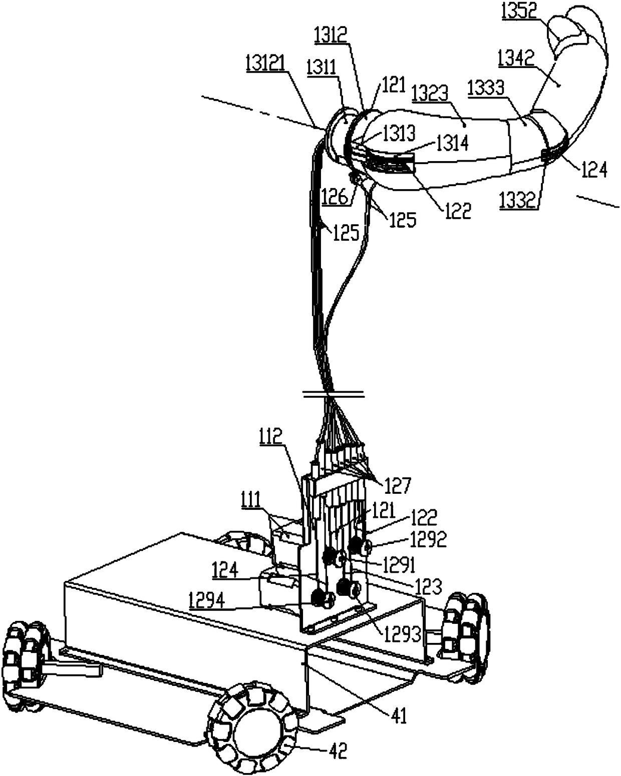

Image

  • Wire control arm and robot
  • Wire control arm and robot
  • Wire control arm and robot

Examples


Embodiment Construction

[0048] In order to more clearly illustrate the embodiments of the present invention or the technical solutions in the prior art, the specific implementation manners of the present invention will be described below with reference to the accompanying drawings. Obviously, the accompanying drawings in the following description are only some embodiments of the present invention, and those skilled in the art can obtain other accompanying drawings based on these drawings and obtain other implementations.

[0049] In order to make the drawing concise, the parts related to the present invention are only schematically shown in each drawing, and they do not represent the actual structure of the product. In addition, to make the drawings concise and easy to understand, in some drawings, only one of the components having the same structure or function is schematically shown, or only one of them is marked. Herein, "a" not only means "only one", but also means "more than one". In this arti...


PUM


Abstract

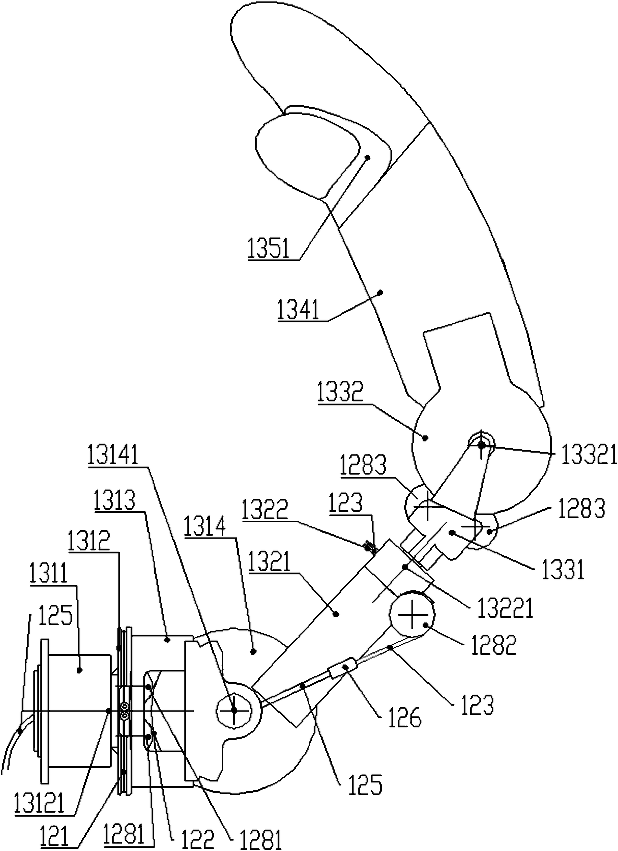
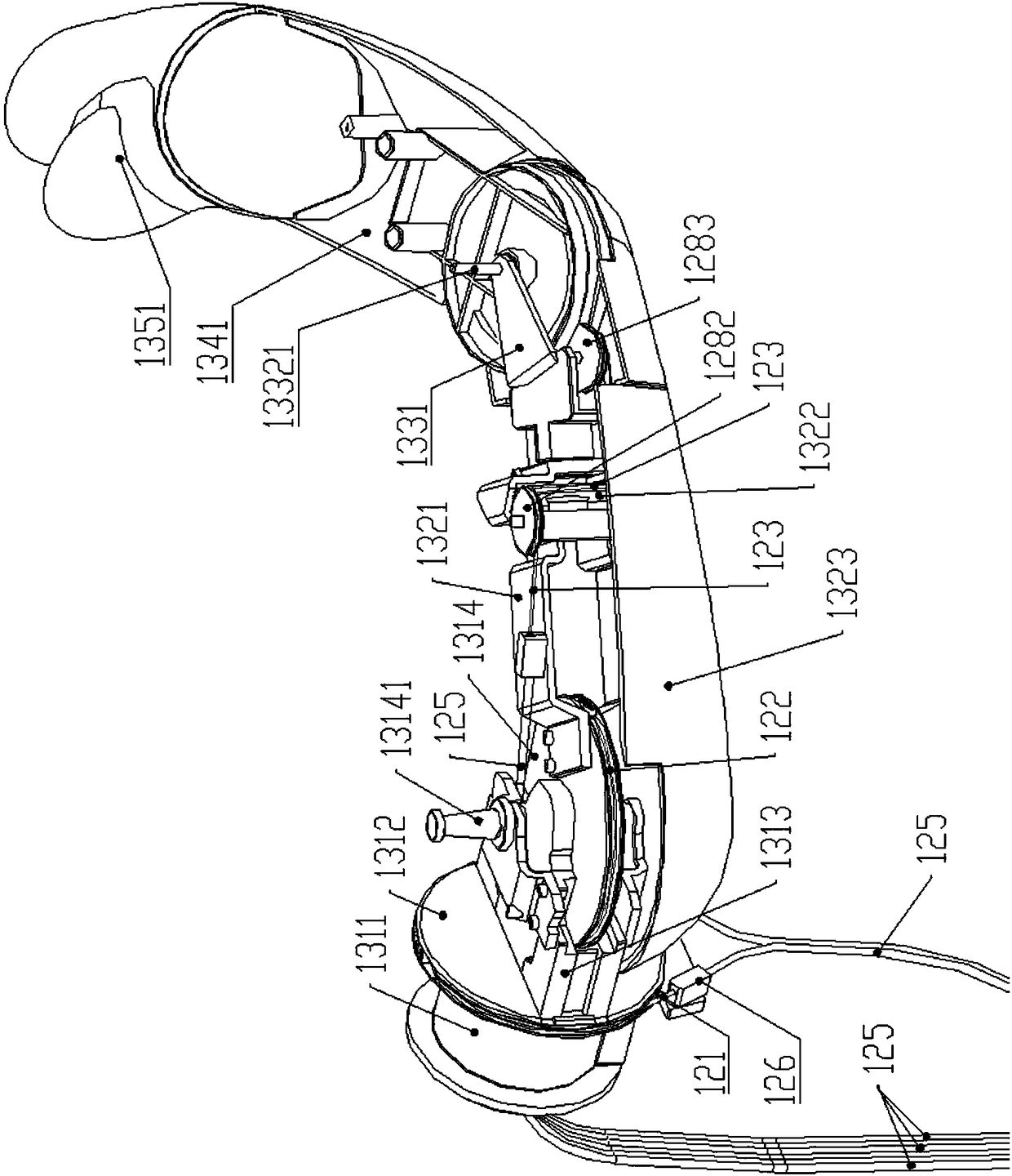
The invention discloses a wire control arm which comprises a drive mechanism, a power wire mechanism and a mechanical arm. The drive mechanism is arranged far away from the mechanical arm; the mechanical arm is formed by serially connecting at least two joint pieces; each two adjacent joint pieces are rotatably connected through a joint wheel; the power wire mechanism comprises coiling wheels corresponding to the joint wheels in quantity; each pair of correspondingly arranged joint wheel and coiling wheel are in tensioning connection through a power wire; and the drive mechanism drives the coiling wheels to rotate, the coiling wheels drive the joint wheels to rotate, and one joint piece rotates relative to the other joint piece arranged adjacently through the corresponding joint wheel. According to the wire control arm provided by the invention, the drive mechanism remotely provides a drive force for the joint pieces of the mechanical arm through the power wires and the joint wheels, so that the weight of the mechanical arm is greatly reduced, the driving moment of the mechanical arm is reduced, and the mechanical arm can realize freedom degrees of more actions.

Description

technical field [0001] The invention relates to the field of mechanical arms, in particular to a wire-controlled arm and a robot. Background technique [0002] A robot is a machine device that performs work automatically. It can accept human command, run pre-programmed programs, and act according to principles formulated with artificial intelligence technology. Its mission is to assist or replace human work in jobs such as manufacturing, construction, or hazardous jobs. [0003] However, the arm joints of existing robots are often driven by a drive mechanism formed by a combination of a motor acceleration and decelerator installed at the arm, which makes the cost of the robot high, and because the drive mechanism is installed at the arm, the weight of the arm is increased, making the arm The driving torque of the robot is limited, and the gears are prone to be damaged by external forces; and due to the shortcomings of the weight, volume and inertia of the motor components,...

Claims


Application Information

Patent Timeline
IPC IPC(8): B25J9/10B25J17/02B25J5/00
CPCB25J5/007B25J9/1045B25J17/0258
Inventor 沈林方继勇
Owner NINGBO GQY VIDEO &TELECOM
Learn More