Circular weft knitting machine with cylindrical coordinate robot

A technology of circular knitting machine and cylindrical coordinates, applied in the directions of knitting, manipulators, manufacturing tools, etc., can solve the problems of insufficiency, increased number of broken yarns, occupying the operator's time, etc., and achieve the effect of quality improvement

Active Publication Date: 2018-08-14
SHISHI BAOXIANG KNITTING MACHINERY
View PDF12 Cites 14 Cited by
  • Summary
  • Abstract
  • Description
  • Claims
  • Application Information

AI Technical Summary

Benefits of technology

This technology uses an apparatus called Yarn Defect Sensor (YSD) for detection purposes during spinning processes. It includes two main components: one component is responsible for moving yarns towards specific locations while another part helps them pass over this location. A special device called Index Disc Driven Mechanism (IDM), also known as Spinning Manipulators, has been developed specifically designed to work together with these devices to achieve better control and efficiency in yam production process.

Problems solved by technology

This patented technical problem addressed in this patents relates to increased wear on operators' hands overtime when manually cleaning fabrics with threaded loops made of synthetic materials like nylon fibers. These threads can damage other components within the machinery causing issues including poorly formed seams between yarn feeders and breaking them down quickly without being able to perform their job effectively. Additionally, these threads may also lead to imperfections called fuzziness which causes holes in the finished product if they are too tight around certain points along its length.

Method used


Image

  • Circular weft knitting machine with cylindrical coordinate robot
  • Circular weft knitting machine with cylindrical coordinate robot
  • Circular weft knitting machine with cylindrical coordinate robot

Examples


Embodiment Construction

[0032] In order to further explain the technical solution of the present invention, it will be described in detail below in conjunction with the accompanying drawings. In the figure, the arrows indicate the moving direction or the rotating direction of the corresponding components.

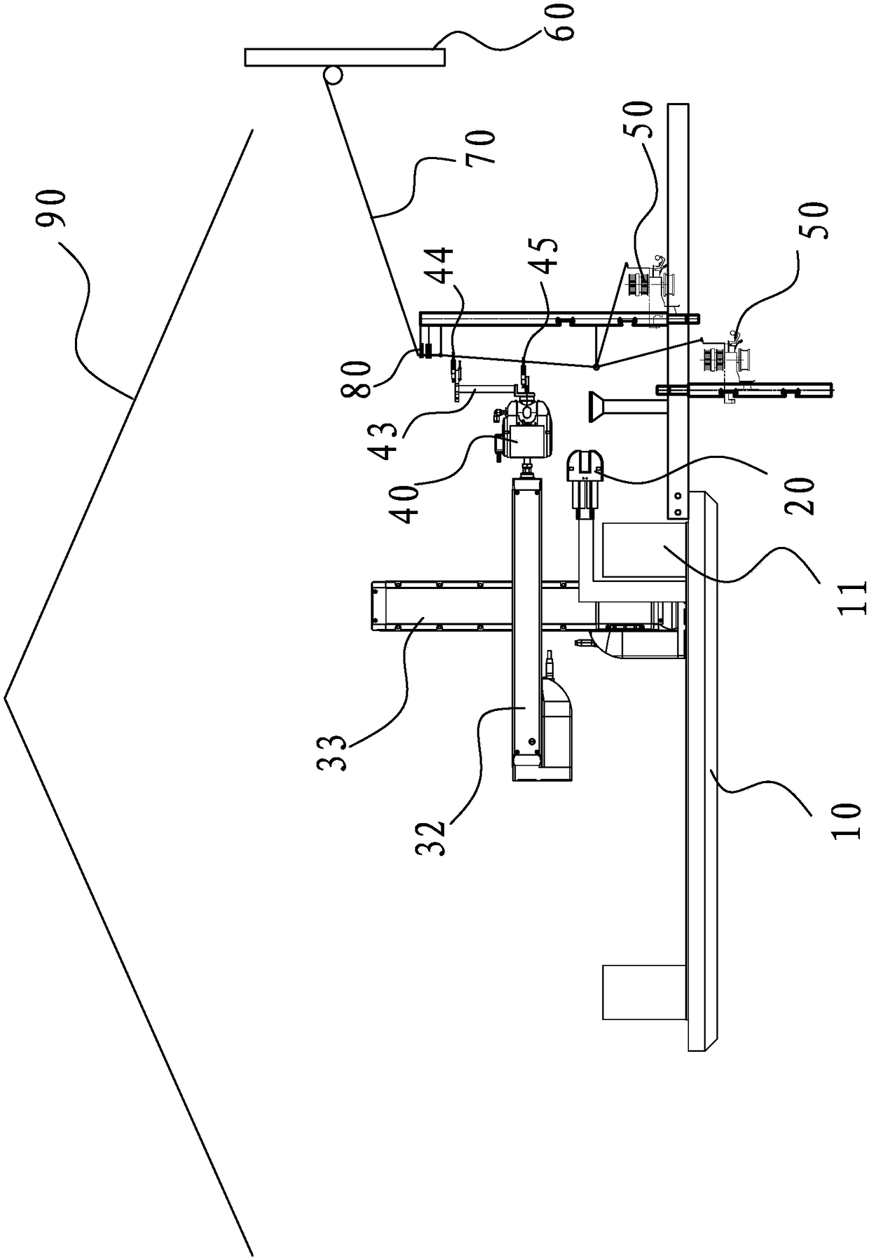
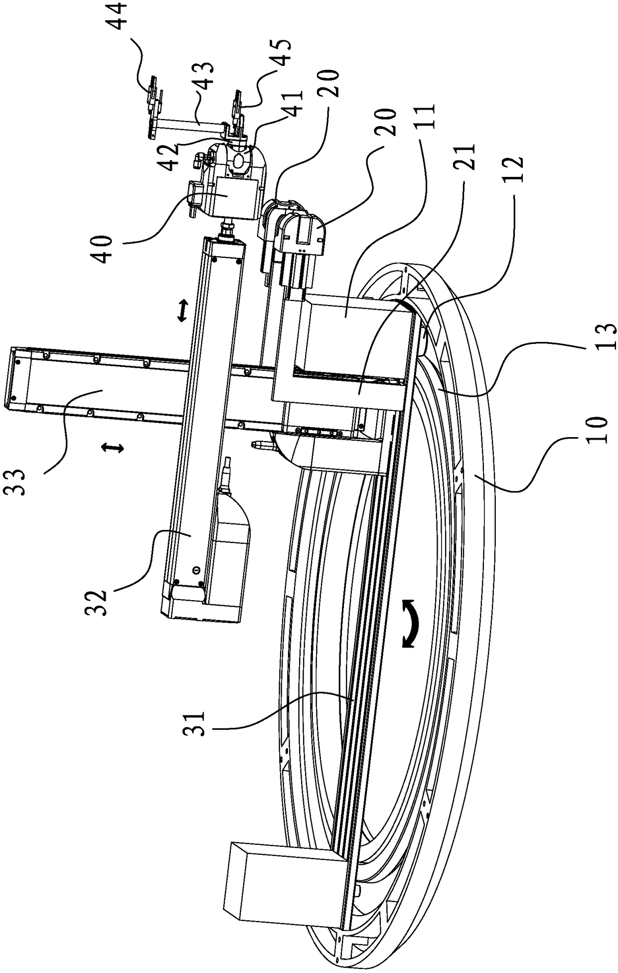
[0033] refer to Figure 1 to Figure 3 , a circular knitting machine with a cylindrical coordinate robot, including a circular knitting machine body, the circular knitting machine body adopts an existing circular knitting machine, which includes a yarn feeding mechanism, a weaving mechanism, a pulling and winding mechanism, and a transmission mechanism, The yarn feeding mechanism includes the creel 60 and the yarn feeder 50 which will be introduced below, and the yarn 70 is threaded on the creel 60 and the yarn feeder 50. These basic structures have been introduced in the existing circular knitting machines. No more detailed description here.

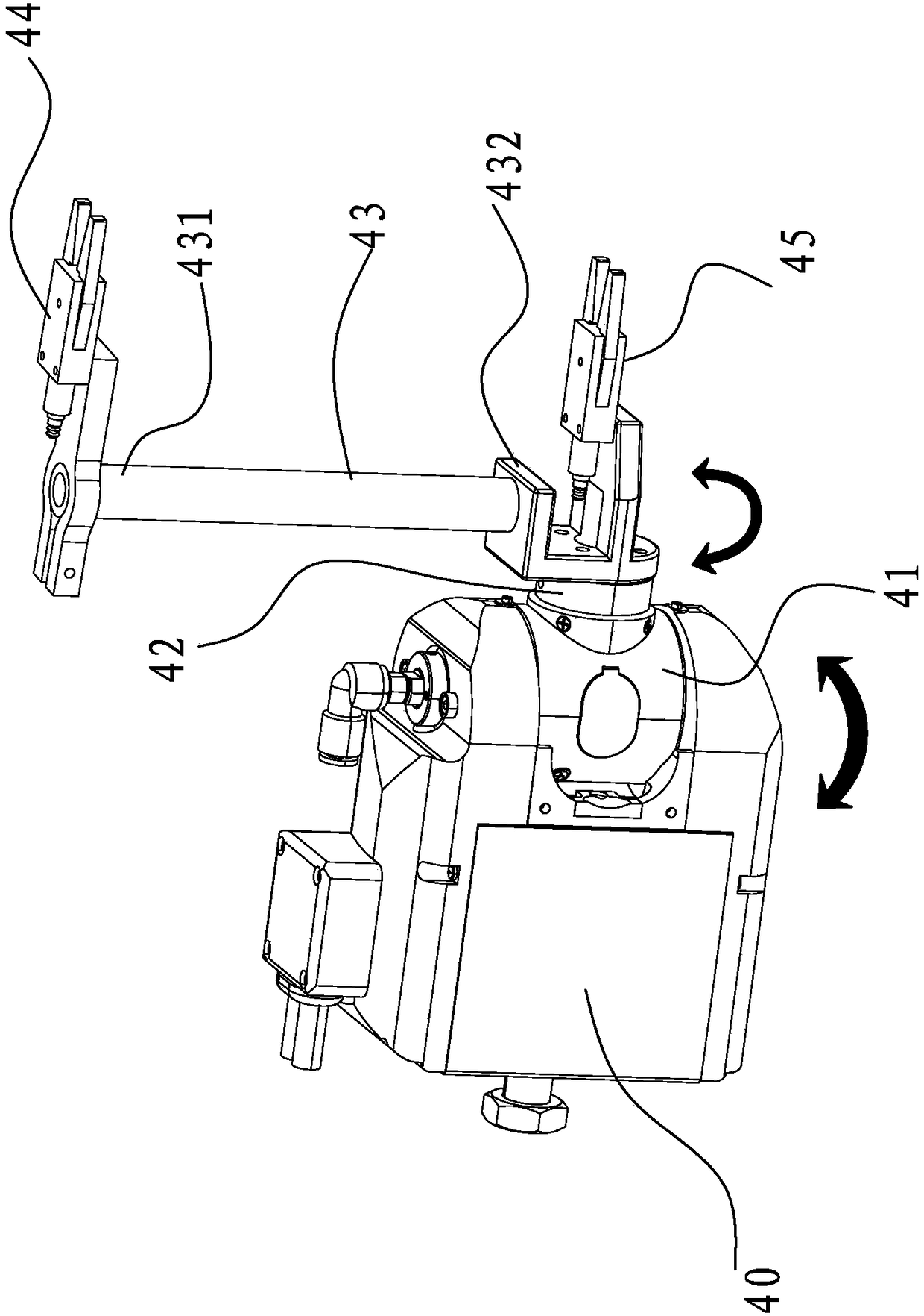
[0034] The present invention also includes a cylindr...


PUM


Abstract

The invention relates to a circular weft knitting machine with a cylindrical coordinate robot. The circular weft knitting machine comprises a circular weft knitting machine body and the cylindrical coordinate robot, the cylindrical coordinate robot comprises a scale division ring rotatably arranged on the circular weft knitting machine body, a first driving mechanism for driving the scale divisionring to rotate around the axis of the scale division ring, a yarn bunching machine for cutting and splicing flaw yarn, a longitudinal beam arranged on the scale division ring, a cross beam up and down movably arranged on the longitudinal beam, a second driving mechanism for driving the cross beam to move up and down, a mechanical arm mechanism arranged on the cross beam in a mode of being capableof moving in the radial direction of the scale division ring and a third driving mechanism for driving the mechanical arm mechanism to move in the radial direction of the scale division ring. A yarnflaw sensor for detecting yarn flaws is arranged between a yarn conveyor of the circular weft knitting machine body and a creel. According to the circular weft knitting machine, the yarn connection action of an operator can be replaced, the quality is close to that of non-knot original yarn, and the quality of fabric is controlled and improved.

Description


Claims


Application Information

Patent Timeline
Owner SHISHI BAOXIANG KNITTING MACHINERY
Why Eureka
Try Eureka