Gas engine intake mixing cavity

A gas engine, mixing chamber technology, applied in engine components, combustion engines, machines/engines, etc., can solve problems such as poor uniformity of each cylinder, excessive emissions, and differences in volatility

Active Publication Date: 2018-08-14
CHINA FIRST AUTOMOBILE
View PDF11 Cites 4 Cited by
  • Summary
  • Abstract
  • Description
  • Claims
  • Application Information

AI Technical Summary

Problems solved by technology

However, these patents can only make the air, gas fuel and EGR mix very uniformly on the spatial axial section of the intake air passage. In particular, the EGR pipe extracts the combustion exhaust gas from the exhaust manifold. The combustion exhaust gas in the pipe fluctuates periodically, and the periodic fluctuation of the combustion exhaust gas will lead to periodic fluctuations of EGR. In addition, the air and gas fuel often have certain fluctuations, and these fluctuations will lead to periodic fluctuations of the intake air mixture.
Although the mixed gas is uniform on the axial section of the air inlet space, the fluctuation will cause the fluctuation of the mixed gas volume (air, gas fuel, EGR) on different axial sections of the air intake channel due to fluctuations, and the intake valves of different cylinders of the engine will open. , The closing time is different, which will lead to a large difference in the amount of mixed gas (air, gas fuel, EGR) entering each cylinder of the gas engine
In engine air intake, if the amount of EGR and gas mixture entering each cylinder is inconsistent, it will cause a series of problems such as engine misfire, knocking, poor uniformity of each cylinder, and excessive emissions, which will affect the normal operation and reliability of the engine.

Method used


Image

  • Gas engine intake mixing cavity
  • Gas engine intake mixing cavity
  • Gas engine intake mixing cavity

Examples


Embodiment Construction

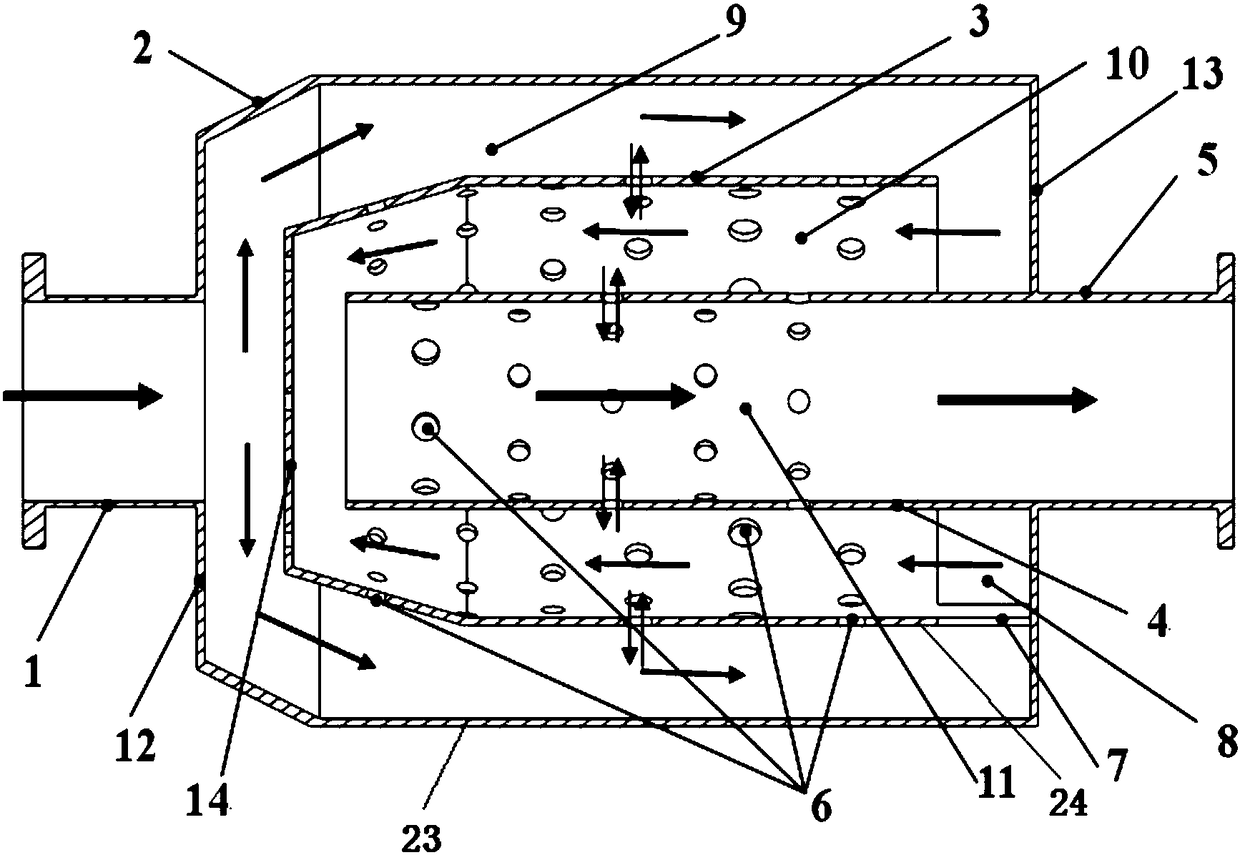
[0029] A gas engine intake mixing chamber of the present invention can refer to the attached Figure 1~7 description, the arrow is the direction of gas movement,

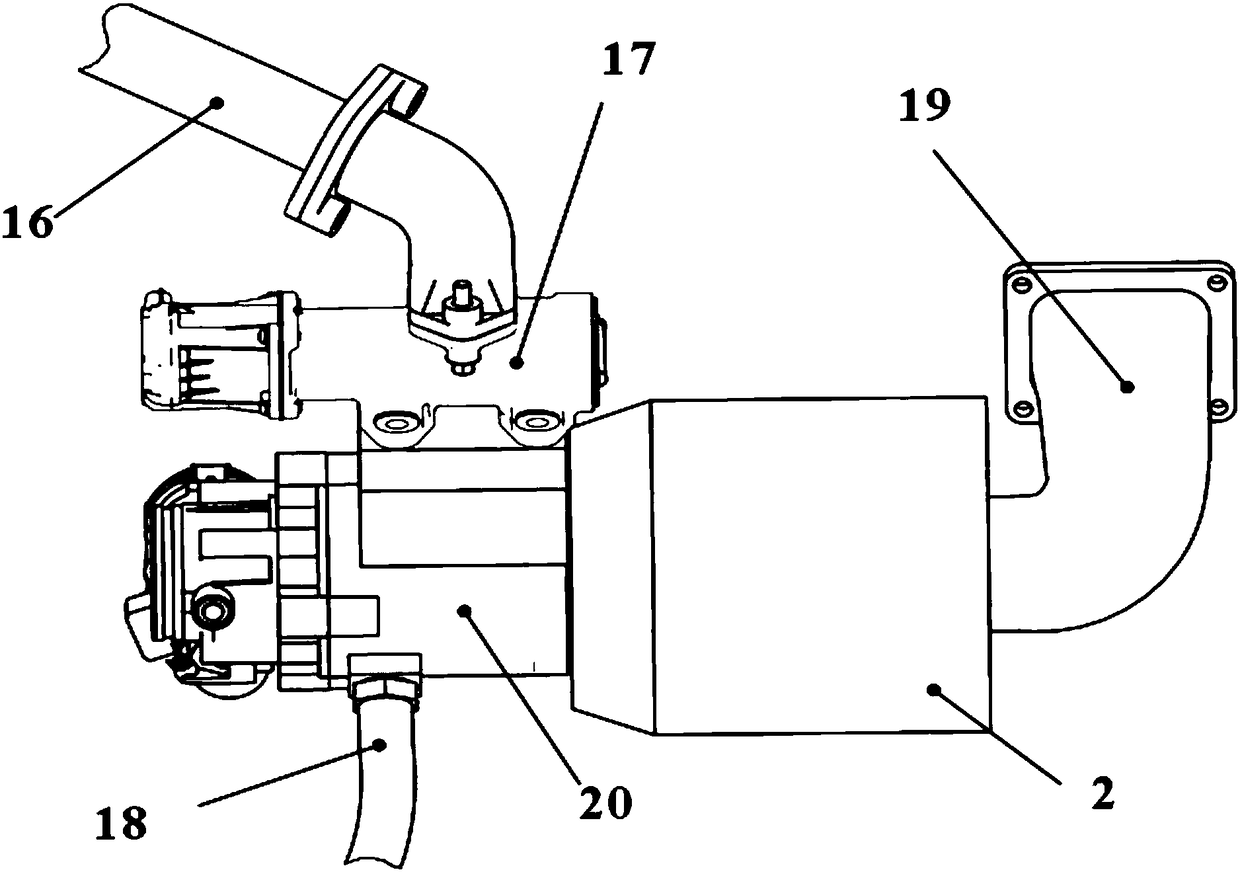
[0030] An air intake mixing chamber for a gas engine, the air intake mixing chamber is arranged between the gas fuel and EGR mixing device and the engine intake pipe elbow 19, including a casing 2, one or more core cover core tube groups ; Figure 1-2 The middle is the structure of a core cover core tube group, Figure 4 The position is a structure of two core-cover core tube groups; when it is larger than two core-cover core tube groups, multiple core-cover core tube groups are set sequentially;

[0031] The casing is sheathed outside the core cover core tube group; each core cover core tube group includes a core cover 3 and a core tube 4, and the core tube 3 is arranged in the core cover 4;

[0032] The housing includes a housing top plate 12, a housing bottom plate 13 and a housing cover plate 23 connecting th...


PUM


Abstract

The invention relates to the technical field of internal combustion engines, in particular to a gas engine intake mixing cavity. The intake mixing cavity is arranged between a gas fuel and EGR mixingdevice and an engine intake elbow. The mixing cavity comprises a shell, and one or more core cover and core tube sets. The outer portion of the core cover and core tube sets is sleeved with the shell.Each core cover and core tube set comprises a core cover and a core tube, wherein the core tube is arranged in the core cover. The multiple core covers and the multiple core tubes are sleeved in sequence. The shell comprises a shell top plate, a shell bottom plate and a shell cover plate connected with the top plate and the bottom plate. Each core cover comprises a core cover top plate, a core cover shell and a connecting plate. The wall surface of each core cover and the wall surface of each core tube are each provided with a plurality of mixing holes. In the engine intake process, cylinderEGRs and gas mixed gas are more uniform in the mixing cavity, the difference, caused by air, gas fuel and EGR fluctuation, of the cylinder EGRs and the gas mixed gas is reduced, the operation consistency of cylinders of the gas engine is effectively improved, and the operation stability and reliability of the gas engine are improved.

Description

technical field [0001] The invention belongs to the field of internal combustion engines, and in particular relates to an air intake mixing chamber for a gas engine. Background technique [0002] With the depletion of energy and the increasingly stringent emission regulations, countries have developed alternative energy sources. As an alternative fuel, combustible gas has become a research hotspot in the engine industry at home and abroad in recent years. Gas fuel is a clean fuel and is very rich in resources. Therefore, alternative gas fuel engines are widely used, and the market share of various vehicles equipped with gas engines is increasing. The current gas engine mainly adopts the premixed combustion method, that is, the fuel gas and air are mixed outside the engine cylinder to form an equivalence ratio mixture, and finally enter the engine cylinder to perform combustion and work. [0003] As the problem of air pollution becomes more and more serious, the emission reg...

Claims


Application Information

Patent Timeline
Patent Type & Authority Applications(China)
IPC IPC(8): F02M21/04
CPCF02M21/042Y02T10/30
Inventor 郭立新李康宁施东晓刘明嘉杨海涛
Owner CHINA FIRST AUTOMOBILE
Why Eureka
Try Eureka