Quick change floating tool for robot casting polishing

A floating and robotic technology, applied in the direction of grinding feed movement, grinding machine parts, manufacturing tools, etc., can solve the problems of track deviation, increase processing cost, tooling manipulator damage, etc., to improve wear resistance and prevent Rust performance, reduce the risk of collision, eliminate the effect of collision and wear

Active Publication Date: 2018-06-19
WUHAN UNIV OF TECH
View PDF6 Cites 5 Cited by
  • Summary
  • Abstract
  • Description
  • Claims
  • Application Information

AI Technical Summary

Problems solved by technology

[0003] 1. Since most of the workpieces to be polished are castings, the consistency of the parts is poor, and it is difficult for the workers to place the parts, and it is difficult to locate or the positioning is not accurate. And the damage caused by the manipulator will also cause shutdown to affect the production progress and bring losses to the enterprise;
[0004] 2. The robot gripper, workpiece and tooling are all rigid bodies. During the contact and clamping process, there is rigid contact between the workpiece and the gripper, and between the workpiece and the tooling. Rigid contact will cause wear to the tooling, resulting in inaccurate positioning; at the same time, the rigidity Contact will cause wear and damage to the gripper. Usually, the gripper cylinder is equipped with a sensor to judge whether the part is grasped accurately according to the cylinder stroke. When the gripper is worn out, it will lead to inaccurate judgments and other problems.
[0005] 3. The grinding workpiece is usually a variety of large-volume parts. Different parts require different special tooling for positioning. Due to the high flexibility of the robot grinding system, it can be used with a quick-change gripper to realize multiple functions of one machine and polish various parts. In actual production , the operation of replacing the tooling is often complicated, and cannot be quickly replaced, resulting in long-term shutdowns that affect the production progress and due to the low positioning accuracy of the tooling, there is an error between the preset grabbing position after the tooling is replaced and before, causing danger or danger during grabbing The trajectory deviates during grinding, which cannot meet the process requirements, resulting in a higher scrap rate and increased processing costs;
[0006] 4. In the actual production process, there will be collision and friction between the workpiece and the tooling when placing the workpiece and grabbing the workpiece, and the surface of the tooling will rust when exposed to the air for a long time, resulting in inaccurate positioning and other problems
There are many above-mentioned problems, which obviously restrict the improvement of production efficiency, so there is an urgent need for a tool that can solve the above-mentioned problems

Method used


Image

  • Quick change floating tool for robot casting polishing
  • Quick change floating tool for robot casting polishing
  • Quick change floating tool for robot casting polishing

Examples


Embodiment Construction

[0038] In order to better understand the patent of the present invention, the patent of the present invention will be further described below in conjunction with the accompanying drawings and specific embodiments.

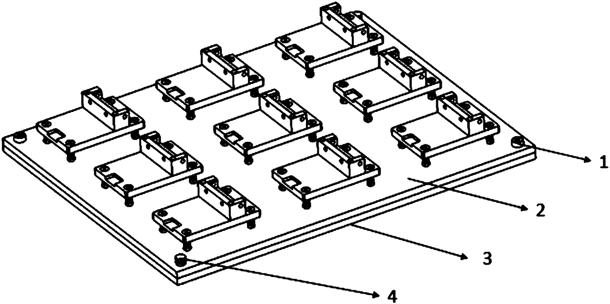
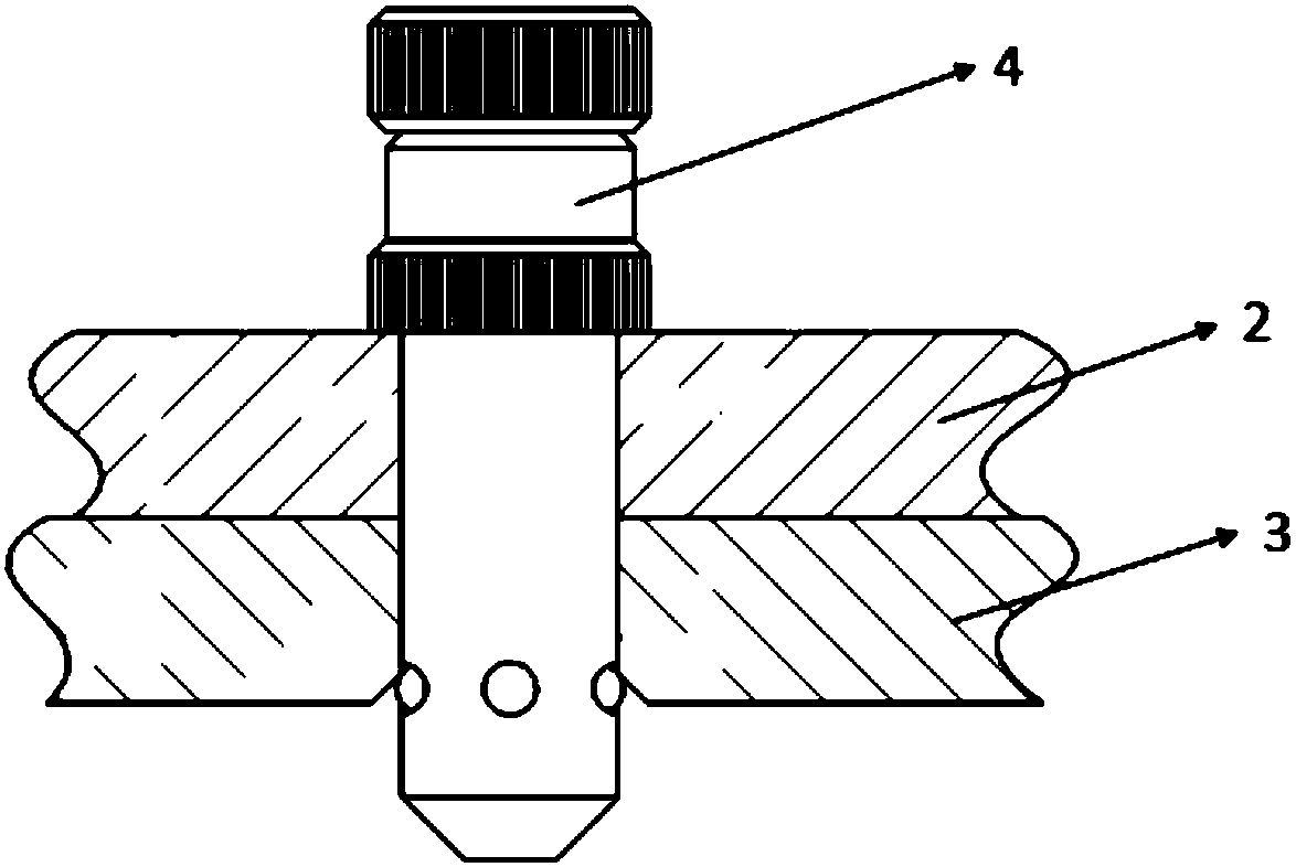
[0039] Such as figure 1 As shown, it is an overall schematic diagram of the quick-change floating tooling, including a mounting plate 3, a tooling plate 2, and nine floating toolings installed on the tooling plate 2, such as figure 2 Shown is a schematic diagram of the fast locking pin 4 locking the mounting plate 3 and the tooling plate 2. On one diagonal line of the tooling plate 2 is a pin hole and the corresponding mounting plate 3 is also a pin hole, and the other diagonal line The upper part is a through hole and the corresponding mounting plate 3 is a threaded hole. First use the quick locking pin 4 to quickly lock the mounting plate 3 and the tooling plate 2, and then screw on the fastening bolt 1 on the other diagonal line. When changing the tooling, tak...


PUM


Abstract

The invention discloses a quick change floating tool for robot casting polishing. The quick change floating tool for robot casting polishing comprises a mounting plate, a tool plate, and multiple floating tools mounted on the tool plate; the detachable tool plate is mounted on the mounting plate; the floating tools comprise spring pressing plates, and positioning blocks fixed thereon; the spring pressing plates are mounted on the tool plate through floating mechanisms; and workpieces to be machined are positioned through the spring pressing plates and the positioning blocks. The floating mechanisms comprise bolts and springs; through holes for enabling the bolts to pass through are formed around the spring pressing plates; the tool plate is provided with thread holes corresponding to the through holes; the bolts are sleeved with the springs after penetrating through the through holes, and are tightened in the thread holes; the bolts are locked on the tool plate through locking the nuts; and the spring pressing plates can move up and down through the springs. As the workpieces are positioned and clamped on the floating tools, when the workpieces are taken and placed, the damage to grippers and the workpieces caused by direct contact of robot grippers and the workpieces can be effectively reduced, and huge economical benefits can be gained for enterprises.

Description

technical field [0001] The invention belongs to the field of mechanical workpiece clamping equipment, and relates to a tooling, in particular to a quick-change floating tooling used for robot casting grinding. Background technique [0002] With the arrival of Made in China 2025, the application of robots is becoming more and more extensive. In the automobile manufacturing industry, most of the auto parts are castings such as automobile hubs, engine blocks, cylinder heads, crankshafts, calipers, brackets, steering knuckles and other parts, which need to be polished for gates, flashes, and burrs. Grinding can improve processing efficiency, ensure processing accuracy, and reduce grinding costs. In the robot automatic grinding system, the tooling plays a vital role. The workpiece to be processed is positioned on the tooling, and the robot gripper grabs the workpiece from the tooling for grinding. At present, in actual production, there are four problems in tooling: [0003] 1...

Claims


Application Information

Patent Timeline
Patent Type & Authority Applications(China)
IPC IPC(8): B24B41/00
CPCB24B41/005
Inventor 吴超群姜尚文郜广磊韩进宇王威强尹绪伟
Owner WUHAN UNIV OF TECH
Why Eureka
Try Eureka