Medical plunger pump and cavity structure thereof
A plunger pump and plunger chamber technology, applied in the field of medical pumps, can solve the problems of easy damage to the mirror effect of the piston chamber wall, increase the roughness of the outer surface of the piston, and reduce the service life of the pump body, so as to reduce the risk of damage and improve Service life, friction reduction effect
- Summary
- Abstract
- Description
- Claims
- Application Information
AI Technical Summary
Problems solved by technology
Method used
Image
Examples
Embodiment 1
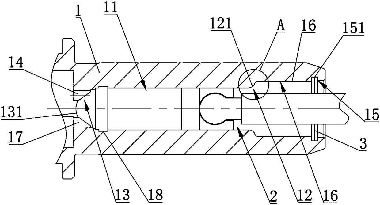
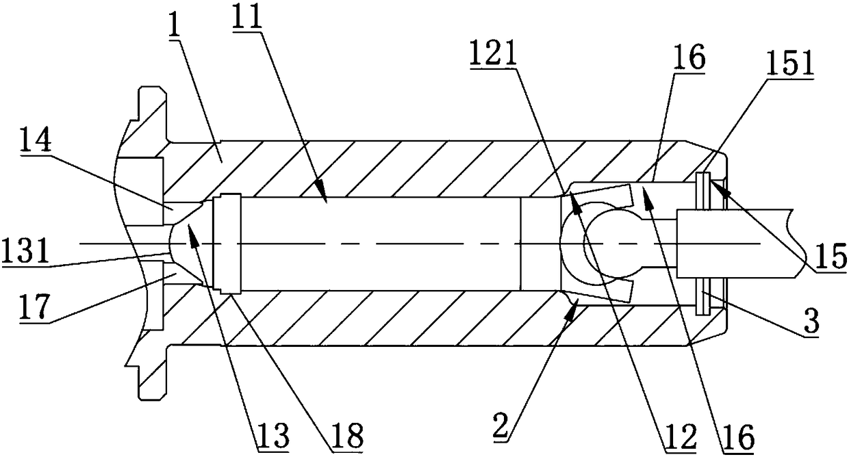
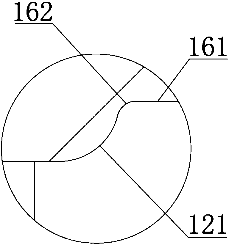
[0037] Preferred embodiments of the present invention refer to Figure 1~5 and Figure 8 , a plunger pump chamber structure for medical use, comprising a pump body 1, the pump body 1 is provided with at least one plunger chamber, the plunger chamber includes a piston working section 11 for reciprocating piston 21 and a piston 21 for reciprocating The joint section 12 connected with the push rod 22 during the movement, the joint section 12 comprises a first arc-shaped wall 121 protruding away from the direction of the piston working section 11, the first end of the first arc-shaped wall 121 is connected to the piston working section The side walls of 11 are smoothly connected, and the second end of the first arc-shaped wall 121 is curved and extends in a direction deviated from the axis of the piston working section 11 .
[0038] The present invention has a simple structure. When the push rod 22 pushes the piston 21 to move in the joint section 12, under the extrusion effect o...
Embodiment 2
[0050] refer to Figure 6 , the difference between this embodiment and Embodiment 1 is that there is no guide section 16 between the engaging section 12 and the space-avoiding section 15, and the second end of the engaging section 12 is connected with the space-avoiding section 15, reducing the piston working section 11 and the plunger. The distance between the opening end of the cavity and the plunger cavity of the same size, the piston 21 moves more smoothly under the action of the push rod 22, reducing the risk of damage to the surface of the piston 21.
[0051] Other structures of this embodiment are the same as those of Embodiment 1, and will not be repeated here.
Embodiment 3
[0053] refer to Figure 7 The difference between this embodiment and Embodiment 1 is that the guide section 16 includes an inclined wall 163, a third arc-shaped wall 164 and a straight wall 161, the straight wall 161 is parallel to the axis of the piston working section 11, and the first arc-shaped wall 121 The second end, the inclined wall 163, the third arc-shaped wall 164 and the straight wall 161 are sequentially connected, and the first arc-shaped wall 121 and the inclined wall 163, the inclined wall 163 and the third arc-shaped wall 164, and the third arc-shaped wall 164 It is respectively tangent to the straight wall 161. Based on the above-mentioned structure, it can be understood that the piston is sequentially advanced in the straight wall 161, the third arc-shaped wall 164, and the inclined wall 163, so that the piston 21 enters the joint section 12 more easily, and then passes through The joint section 12 realizes the connection and fixation of the piston 21 and th...
PUM
 Abstract
Description
Claims
Application Information
 - R&D
- Intellectual Property
- Life Sciences
- Materials
- Tech Scout
- Unparalleled Data Quality
- Higher Quality Content
- 60% Fewer Hallucinations
Browse by: Latest US Patents, China's latest patents, Technical Efficacy Thesaurus, Application Domain, Technology Topic, Popular Technical Reports.
© 2025 PatSnap. All rights reserved.Legal|Privacy policy|Modern Slavery Act Transparency Statement|Sitemap|About US| Contact US: help@patsnap.com


