
Horizontal type sand pump with double-end-face mechanical seal structure

A mechanical seal and double-end face technology, which is applied to mechanical equipment, non-variable pumps, components of pumping devices for elastic fluids, etc. Sealing end face dry wear and other problems to achieve the effect of improving reliability and maintaining environmental stability

Pending Publication Date: 2018-08-14
温刚
View PDF5 Cites 2 Cited by
  • Summary
  • Abstract
  • Description
  • Claims
  • Application Information

AI Technical Summary

Problems solved by technology

[0003] 1. When the conveyed medium freezes in the cold winter, the single-end mechanical seal is surrounded and frozen by the frozen medium. When starting the sand pump, the mechanical seal is bound by the frozen medium, and the single-end mechanical seal has no liquid The medium is lubricated and cooled, the end face of the mechanical seal is dry-frictioned sharply, and the mechanical seal is quickly damaged and leaked
[0004] 2. When the conveyed medium is dry in hot summer, the single-end mechanical seal is surrounded and dried up by the dry medium. When the sand pump is started, the mechanical seal is bound by the dry medium, and the single-end mechanical seal has no liquid medium. Lubrication and cooling, rapid dry friction on the end face of the mechanical seal, rapid damage to the mechanical seal and leakage
[0005] 3. Regardless of the reason, when there is no medium entering the pump inlet, that is, the pump is in the state of evacuation and no medium operation, the single-end mechanical seal has no medium lubrication and cooling, the end face of the mechanical seal is dry-worn rapidly, and the mechanical seal is quickly damaged and leaked
[0006] 4. When the drilling fluid with high specific gravity is transported, the drilling fluid will stay and stick to the end face of the mechanical seal, causing the heat of the mechanical seal to not dissipate, resulting in leakage of the mechanical seal

Method used


Image

  • Horizontal type sand pump with double-end-face mechanical seal structure
  • Horizontal type sand pump with double-end-face mechanical seal structure
  • Horizontal type sand pump with double-end-face mechanical seal structure

Examples


Embodiment Construction

[0029] Below in conjunction with accompanying drawing and specific embodiment, the present invention will be further described

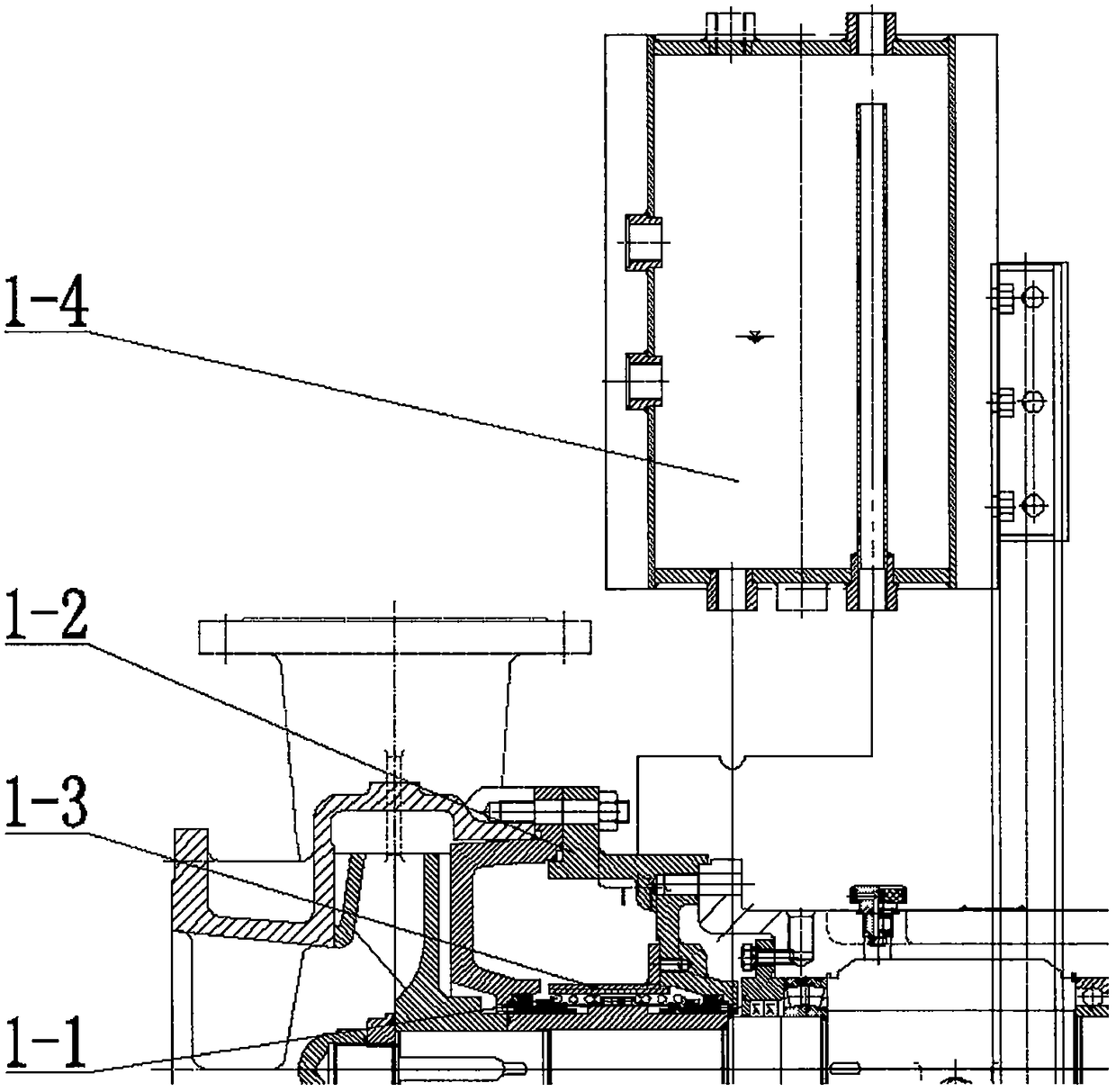
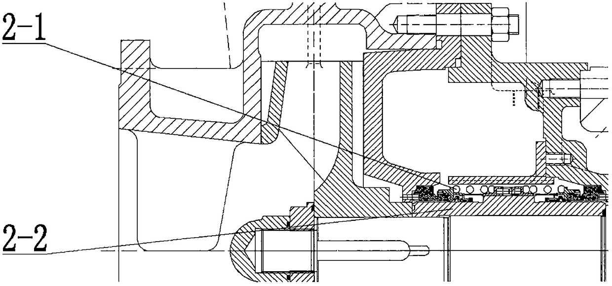
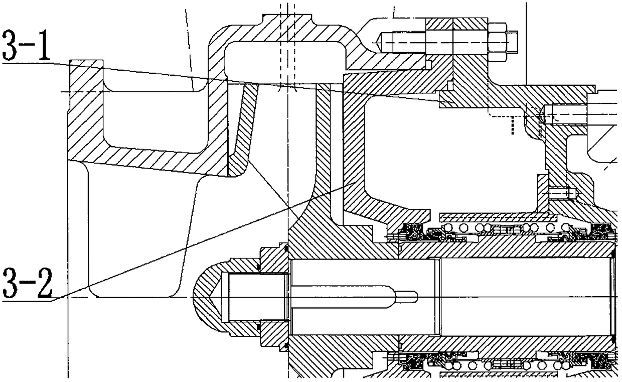
[0030] figure 1 Middle: Horizontal sand pump with double-end mechanical seal structure, including double-end mechanical seal structure 1-1, seal box assembly 1-2, pumping sleeve structure 1-3 and cooling tank assembly 1-4, double The end face mechanical seal structure 1-1 is installed inside the pumping sleeve structure 1-3, together with the pumping sleeve structure 1-3, it is placed inside the sealing box assembly 1-2, and the outside of the sealing box assembly 1-2 is connected with the pipeline through the The cooling tank assembly 1-4, the sealing box assembly 1-2 and the cooling tank assembly 1-4 are filled with engine oil as a circulating cooling medium, and the engine oil passes through the pumping sleeve structure 1-3 outside the double-end mechanical seal structure 1-1 The engine oil in the sealed box assembly 1-2 can flow from one side to...


PUM


Abstract

The invention belongs to the fields and industries of petroleum exploration, petroleum extraction, petroleum refining and petroleum product transportation and provides a horizontal type sand pump a double-end-face mechanical seal structure. The horizontal type sand pump with the double-end-face mechanical seal structure aims at overcoming various defects and shortcomings found in the using processof a single-end-face mechanical seal, improving operation stability of the complete machine pump, enhancing adaptability to harsh working conditions, prolonging the service life and meeting using requirements. The horizontal type sand pump with the double-end-face mechanical seal structure is characterized in that the horizontal type sand pump comprises the double-end-face mechanical seal structure, a seal box assembly, a pumping sleeve structure and a cooling tank assembly.

Description

technical field [0001] The invention belongs to the fields of petroleum exploration, petroleum exploitation, petroleum refining, and petroleum product transportation. The horizontal sand pump with double-end mechanical seals is used, especially in the oil drilling and exploration industry. The drilling fluid solid control equipment is equipped with a double-end mechanical seal. Sealed horizontal sand pump. Background technique [0002] At present, in the oil drilling and exploration industry, drilling fluid is used as the blood of drilling rigs, which can lubricate the drill bit underground, bring rock debris back to the surface, filter and separate, and then press it into the underground for recycling. Drilling fluid is a kind of high viscosity. , a mixed liquid with high specific gravity and high particle content, also called mud, and the pump that transports drilling fluid is called sand pump. At present, sand pumps adopt single-end mechanical seal structure. Under harsh ...

Claims


Application Information

Patent Timeline
IPC IPC(8): F04D29/10F04D29/06F04D29/58
CPCF04D29/061F04D29/106F04D29/586
Inventor 温刚
Owner 温刚
Learn More