Check patentability & draft patents in minutes with Patsnap Eureka AI!

Multi-stage transmission structure

A transmission device, transmission stage technology, applied in the direction of transmission device, belt/chain/gear, mechanical equipment, etc., can solve the problems of reduced service life, disadvantageous toothed belt, etc., and achieve the effect of reducing weight

Active Publication Date: 2018-08-14
CONTITECH ANTRIEBSSYST
View PDF9 Cites 4 Cited by
  • Summary
  • Abstract
  • Description
  • Claims
  • Application Information

AI Technical Summary

Problems solved by technology

In this type of planetary belt drive, the simultaneous meshing of the belt with the outer toothed planet wheels and the inner toothed ring gear leads to differences in the linear speeds of the individual gears leading to unfavorable internal wear of the toothed belt, which reduces the service life. force ratio and tension ratio

Method used


Image

  • Multi-stage transmission structure
  • Multi-stage transmission structure
  • Multi-stage transmission structure

Examples


Embodiment Construction

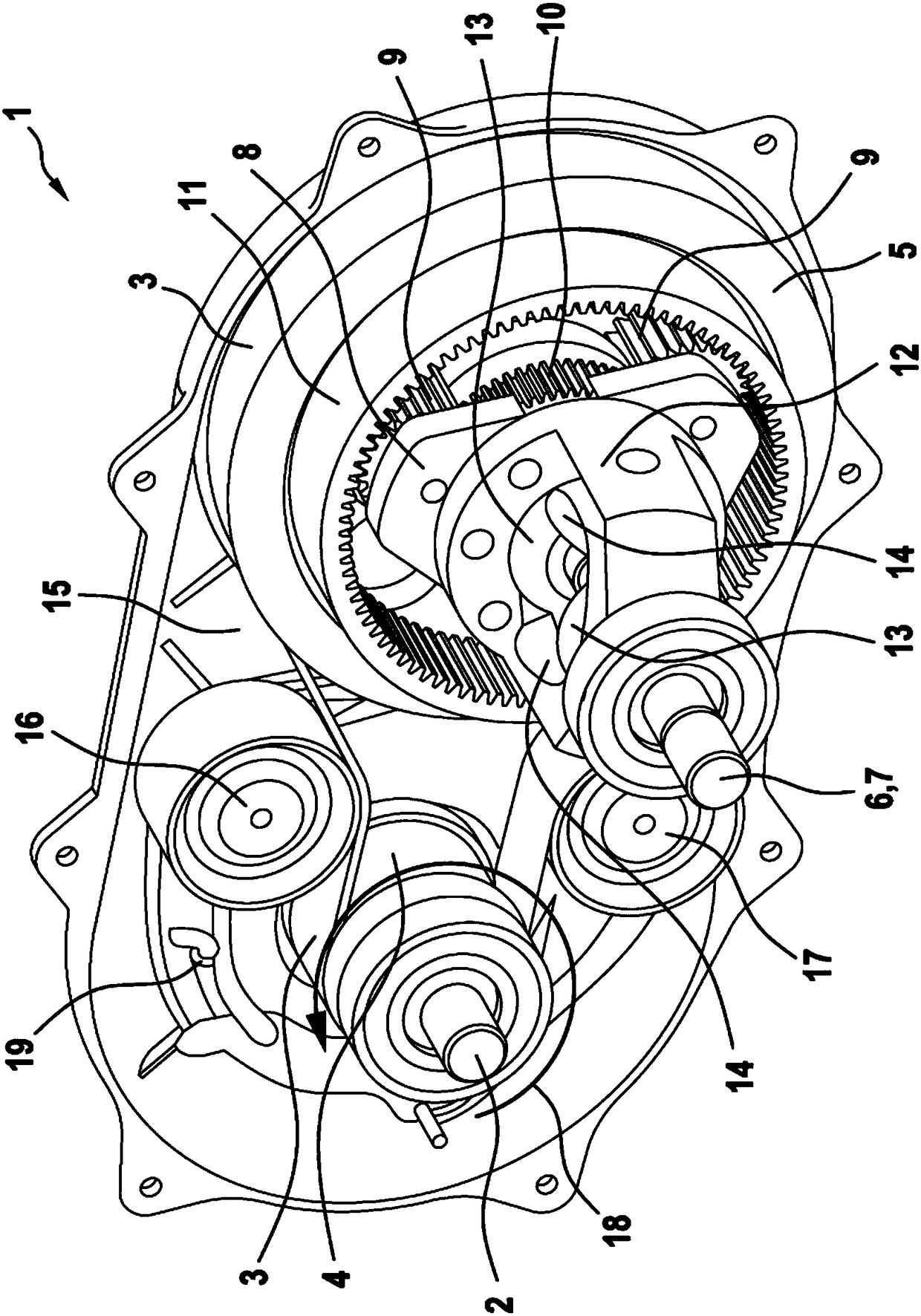
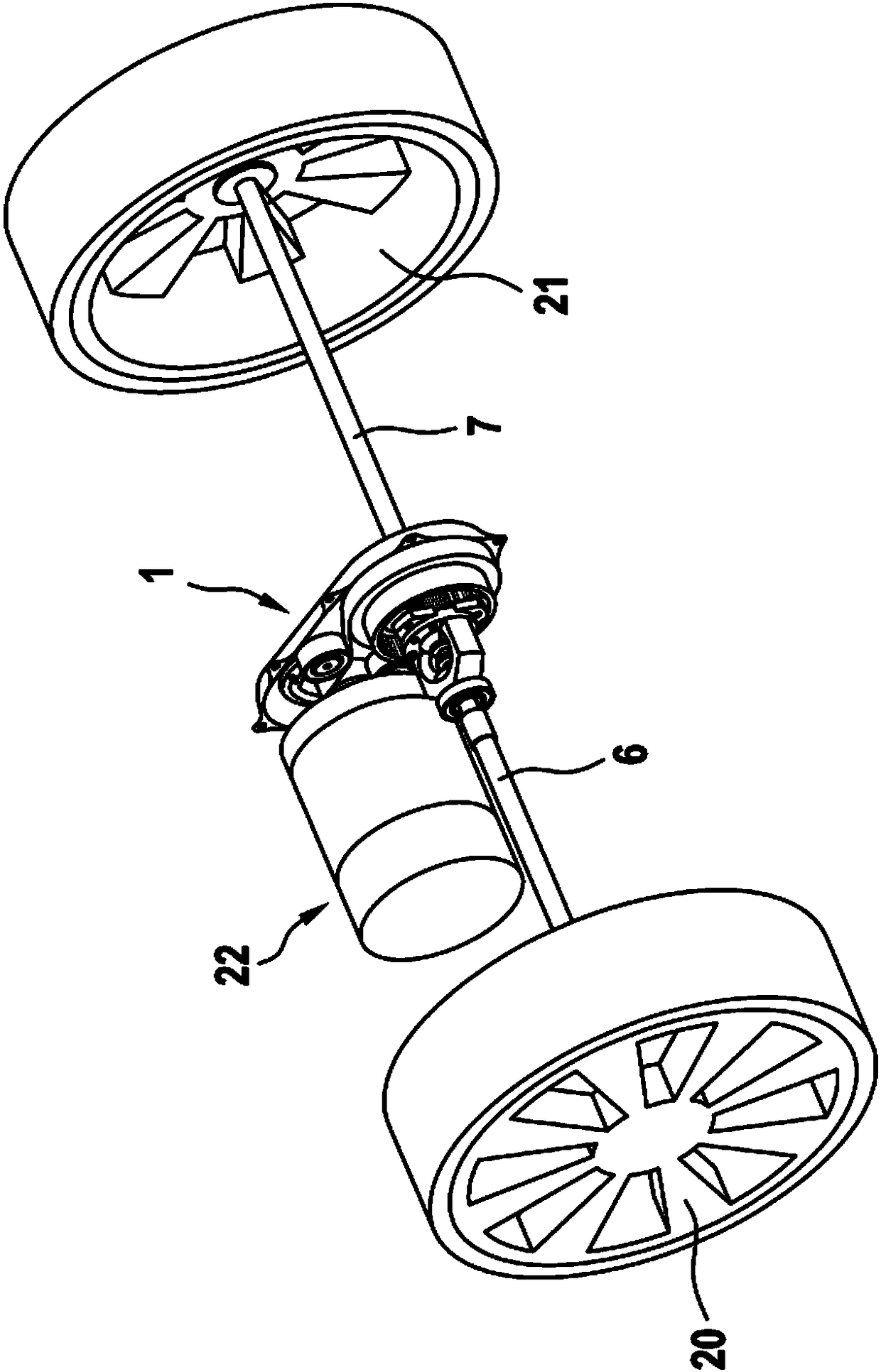
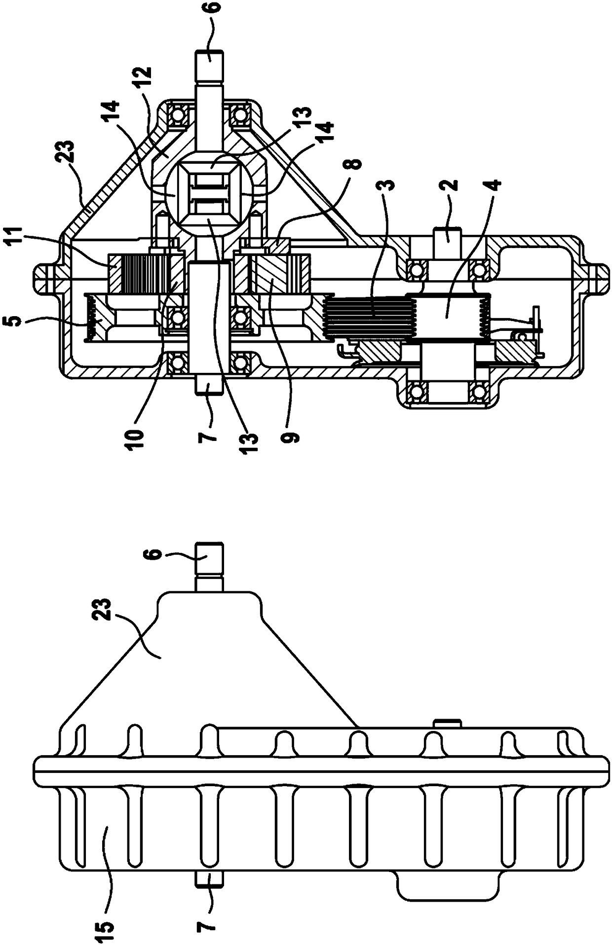
[0046] figure 1 In perspective views, especially with image 3 A constructive embodiment of the drive arrangement 1 according to the invention is shown in conjunction with the view, in which a tension belt drive is firstly provided on the drive side, ie starting from the drive or drive shaft 2 as Variable speed transmission. Here, the tension belt drive has a tension belt in the form of a V-ribbed belt 3 which is wound around the drive pulley 4 and the output pulley 5 of the tension belt drive in a friction fit or form fit, respectively, in order to transmit the torque. and number of revolutions.

[0047] Based on the output side of the tension belt transmission, that is to say in this embodiment, a first planetary gear transmission is arranged between the output pulley 5 and one or two output shafts 6,7 of the tension belt transmission , which has a first planet carrier 8 for accommodating and supporting the first planet wheels 9 . Here, the planetary gear and the sun gea...


PUM


Abstract

Disclosed is a multi-stage transmission gear structure for power transfer between shafts, wherein at least one of a transmission stage configured as a planetary gear transmission and a transmission stage configured as a tension belt transmission in a force or power flow is arranged in the same transmission housing and preferably each has a fixed, non-switchable gear ratio.

Description

technical field [0001] The invention relates to a multi-stage transmission structure for power transmission between shafts. Background technique [0002] Multi-stage transmission structures for power transmission are known in a large number of embodiments from the prior art. These are usually steel gears, for example spur gears or bevel gears for converting speed and torque. Here, the multi-stage transmission can be designed to be shiftable or provided with fixed transmission ratios. [0003] In vehicles in particular, it is important that the transmissions used here have as little weight as possible and nonetheless be able to meet all other performance figures as well as high transmission ratios. Precisely to achieve high transmission ratios, multiple stages are often required, which increases the weight of such transmissions. As a result, the wheelbase of the gears is also increased, which makes the required space relatively large. This is also highly undesirable in a ...

Claims


Application Information

Patent Timeline
IPC IPC(8): F16H37/02F16H7/10
CPCF16H7/10F16H37/02F16H2007/0874F16H2007/0865F16H2007/0893F16H37/082
Inventor 菲利普·弗赖海特蒂姆·菲斯奥利维尔·弗拉门特
Owner CONTITECH ANTRIEBSSYST
Features
  • R&D
  • Intellectual Property
  • Life Sciences
  • Materials
  • Tech Scout
  • Unparalleled Data Quality
  • Higher Quality Content
  • 60% Fewer Hallucinations
Learn More