
Motion trajectory tracking device and method thereof

A motion trajectory and tracking device technology, which is applied in the field of optical-magnetic combination motion trajectory tracking device, can solve the problems of low precision of MEMS sensors, achieve the effects of improving magnetization efficiency, high production efficiency, and increasing magnetization magnetic field strength

Active Publication Date: 2018-08-14
周小英
View PDF4 Cites 1 Cited by
  • Summary
  • Abstract
  • Description
  • Claims
  • Application Information

AI Technical Summary

Problems solved by technology

However, the accuracy of the existing MEMS sensor is not high, and it can only be used in some fields that do not require high precision.

Method used


Image

  • Motion trajectory tracking device and method thereof
  • Motion trajectory tracking device and method thereof
  • Motion trajectory tracking device and method thereof

Examples


Embodiment Construction

[0067] The technical solutions provided by the present invention will be further described below in conjunction with the accompanying drawings.

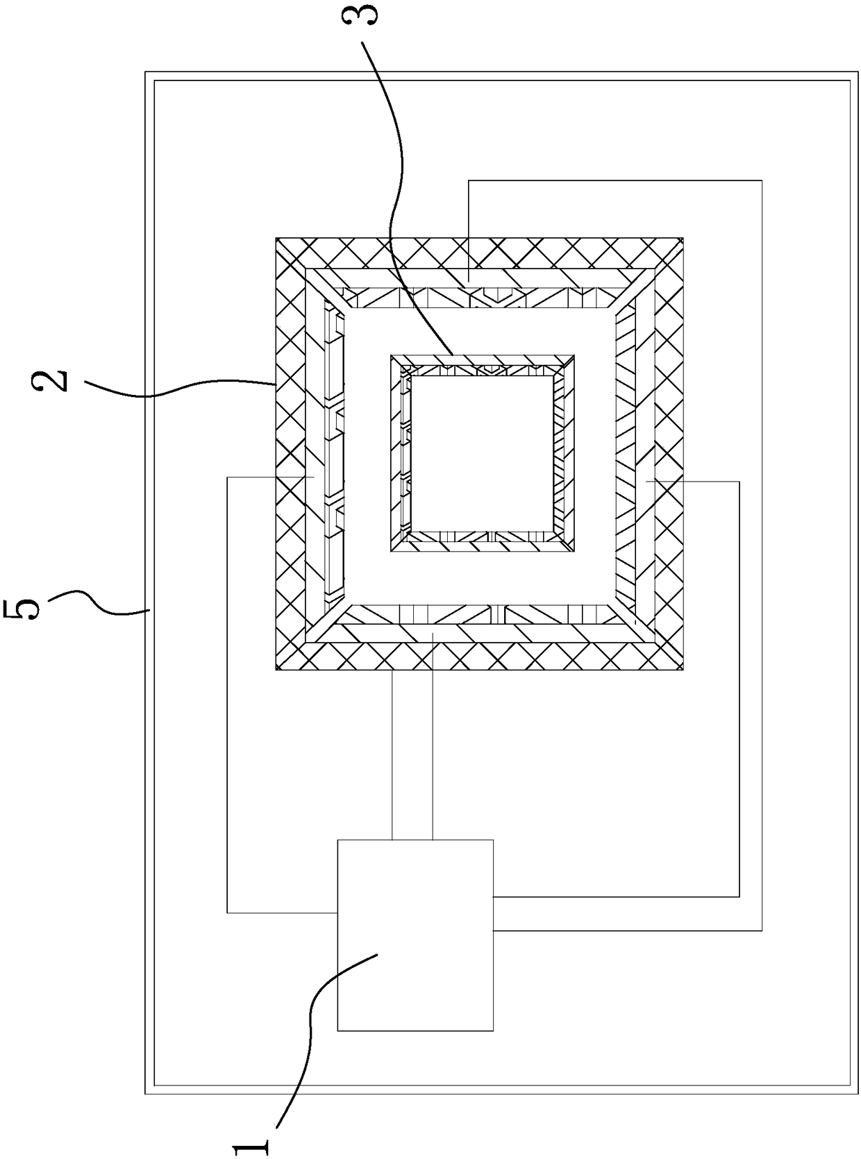
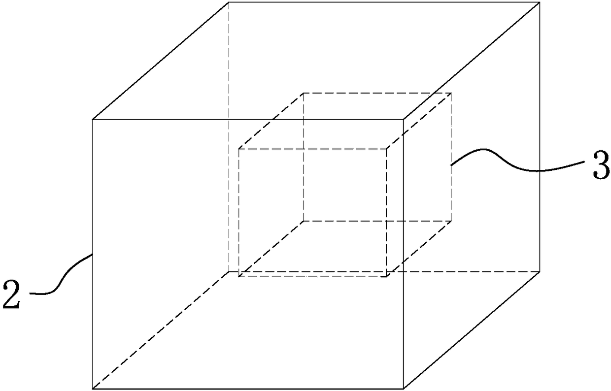
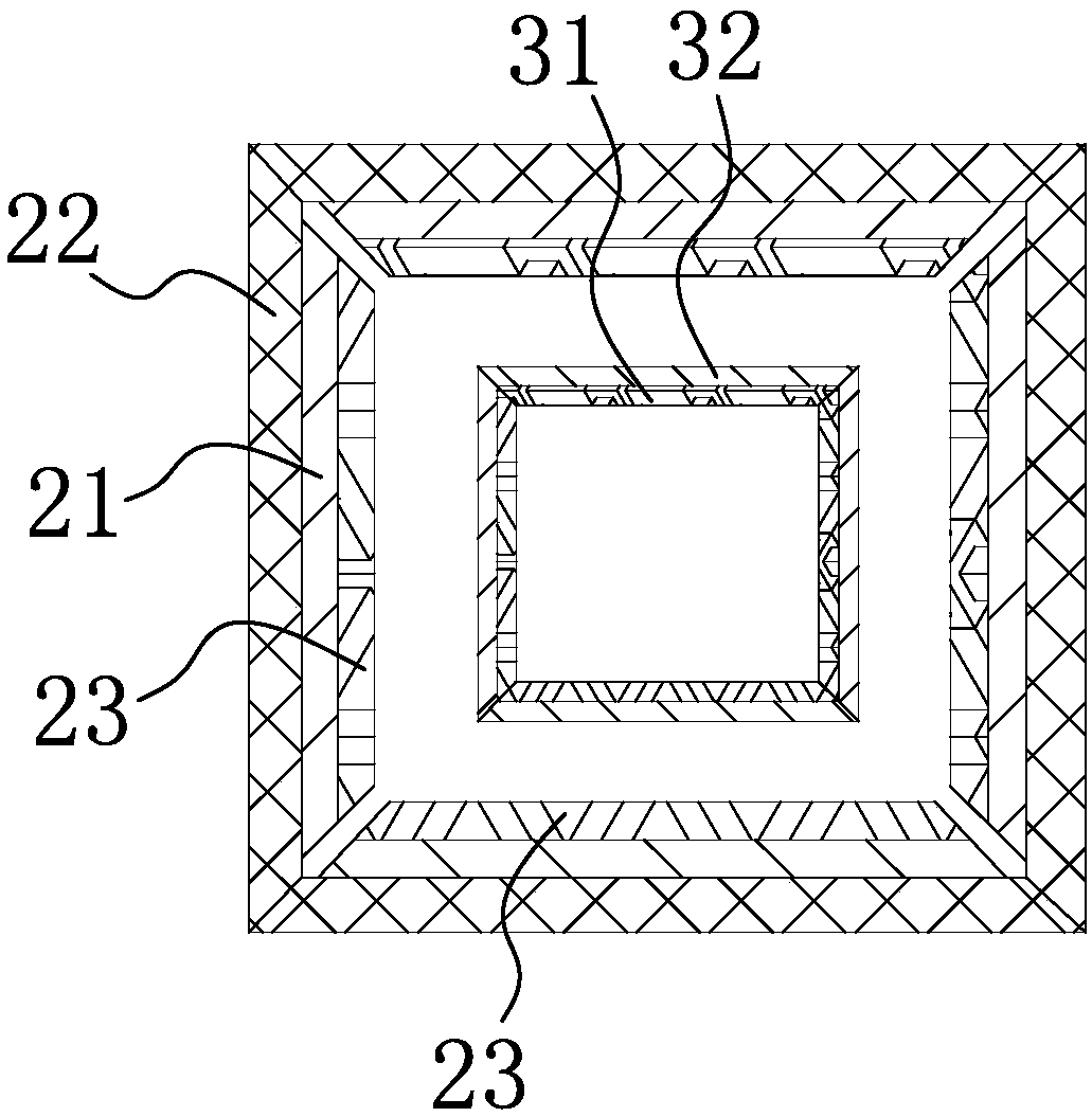
[0068] see Figure 1-3 , is shown as a structural block diagram of the motion trajectory tracking device of the present invention, including a control board 1, a magnetic cavity 2 and a magnetic levitation body 3 arranged in the magnetic cavity 2, the magnetic cavity 2 is a closed magnetic cavity 2, and a carrier The fixed connection is used to sense the change of the moving state of the carrier; the control board 1 is assembled with the airtight magnetic cavity 2 and is electrically connected to the optical positioning arrays arranged on the six sides of the magnetic cavity 2, and is used to obtain the magnetic levitation in real time. The position of the magnetic levitation body in the hexahedral magnetic field space is calculated, and the trajectory of the carrier is calculated according to the position change of the magnetic levi...


PUM


Abstract

The invention discloses a motion trajectory tracking device and a method thereof. The device comprises an optical positioning device and a six-degree-of-freedom magnetic suspension structure; the six-degree-of-freedom magnetic suspension structure comprises a magnetic cavity fixedly connected with a motion carrier and a magnetic suspension body which suspends in the magnetic cavity, the six surfaces of the magnetic suspension body having residual magnetic fields; the magnetic cavity forms a hexahedral space and is movable relative to the magnetic suspension body; and the polarity of a second permanent magnetic layer disposed on any surface of the magnetic cavity is the same as the polarity of a first permanent magnetic layer arranged on one surface of the magnetic suspension body which isopposite to the one surface of the magnetic cavity, and therefore, repulsive magnetic forces can be simultaneously generated at the six surfaces of the magnetic suspension body, and a six-surface magnetic force balance state can be realized. With the above technical schemes adopted, the three-dimensional magnetic suspension structure is ingeniously designed, so that six-degree-of-freedom suspension can be realized, and therefore, the motion state change of the carrier is converted into the position change of the magnetic suspension body in the magnetic cavity; and the position change of the magnetic suspension body in the magnetic cavity is detected in real time through the optical positioning device, so that the trajectory tracking of the motion carrier is realized.

Description

technical field [0001] The invention belongs to the field of motion track tracking, and more specifically relates to a light-magnetic combined motion track tracking device and method thereof. Background technique [0002] In current technology, GPS is usually used for positioning and navigation, but GPS needs satellite assistance to complete and the cost is high; there are also external position sensors (such as radar, ultrasonic, laser, and camera) to track the trajectory of moving objects. These methods have complex structures , and there are strict restrictions on the movement area of ​​objects, which is not convenient for actual use. With the continuous development of unmanned driving technology, the moving body needs to position itself during the movement to achieve inertial navigation. In recent years, inertial navigation technology has been widely used in aerospace, navigation, automotive electronics, robotics, deep sea exploration and other fields. For important app...

Claims


Application Information

Patent Timeline
IPC IPC(8): G01S5/16
CPCG01S5/16
Inventor 周小英
Owner 周小英
Learn More