
Optical coaxial calibration device and application method thereof

A calibration device, coaxial technology, applied in radio wave measurement systems, instruments, etc., can solve the problems of large size, inconvenient movement, heavy weight, etc., and achieve the effect of simple system structure, easy operation and light weight

Pending Publication Date: 2018-08-14
北京国泰蓝盾科技有限公司
View PDF7 Cites 6 Cited by
  • Summary
  • Abstract
  • Description
  • Claims
  • Application Information

AI Technical Summary

Problems solved by technology

One of the important technical indicators is the need to ensure the consistency of the transmitting and receiving optical axes. The existing optical coaxial calibration device usually includes a large-diameter concave reflector (or large-diameter focusing mirror, usually with a diameter of above 100mm), bulky, heavy, and inconvenient to move

Method used


Image

  • Optical coaxial calibration device and application method thereof
  • Optical coaxial calibration device and application method thereof

Examples


Embodiment Construction

[0033] The specific implementation manners of the present invention will be further described in detail below in conjunction with the accompanying drawings.

[0034] The following description and drawings illustrate specific embodiments of the invention sufficiently to enable those skilled in the art to practice them. Other embodiments may incorporate structural, logical, electrical, process, and other changes. The examples merely represent possible variations. Individual components and functions are optional unless explicitly required, and the order of operations may vary. Parts and features of an embodiment may be included in or substituted for those of other embodiments. The scope of embodiments of the present invention includes the full scope of the claims, and all available equivalents of the claims. These embodiments of the present invention may be referred to herein, individually or collectively, by the term "invention", which is for convenience only and is not inten...


PUM


Abstract

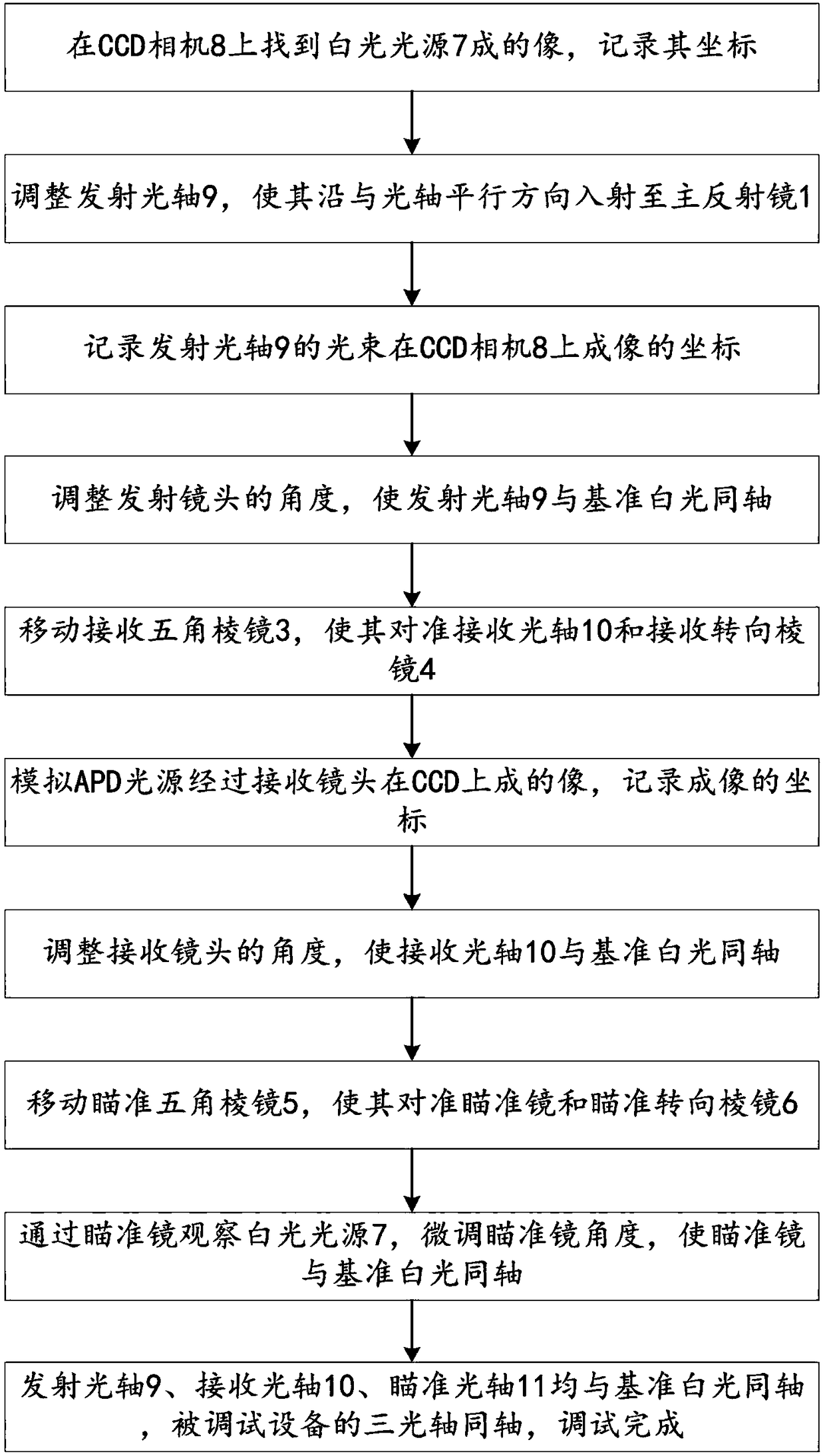
The invention provides an optical coaxial calibration device and an application method thereof. The device includes a main mirror, a beam splitter, a receiving pentagonal prism, a receiving steering prism, an aiming pentagonal prism, an aiming steering prism, a white light source and a CCD camera; an emitting optical axis is emitted to the main mirror and reflected by the main mirror to focus to the CCD camera; a receiving optical axis passes through the receiving pentagonal prism and the receiving steering prism and is reflected by the main mirror to the CCD camera; an aiming optical axis passes through the aiming pentagonal prism and the aiming steering prism and is reflected by the main mirror to the CCD camera; the emitting optical axis, the receiving optical axis and the aiming optical axis are adjusted to be coaxial with the white light source as the reference; the beam splitter divides a to-be-measured light source into two parts and makes one part of the to-be-measured light source reach the position of the white light source and the other part of the to-be-measured light source reach the position of the CCD camera. According to the optical coaxial calibration device and the application method thereof, the main mirror is small in diameter and weight and convenient to move, and the whole system structure is simple and convenient to operate.

Description

technical field [0001] The invention relates to a calibration device, in particular to an optical coaxial calibration device and a method for using the same. Background technique [0002] In the work of laser range finder, laser radar and other related equipment, the target is irradiated with laser light, and the reflected light signal of the target to the laser is received at the same time. One of the important technical indicators is the need to ensure the consistency of the transmitting and receiving optical axes. The existing optical coaxial calibration device usually includes a large-diameter concave reflector (or large-diameter focusing mirror, usually with a diameter of Above 100mm), bulky, heavy, and inconvenient to move. Contents of the invention [0003] In order to overcome the problems in the related art at least to a certain extent, the present application provides an optical coaxial calibration device and a method for using the same. [0004] The object of ...

Claims


Application Information

Patent Timeline
Patent Type & Authority Applications(China)
IPC IPC(8): G01S7/497
CPCG01S7/497
Inventor 张帆叶一东崔家珮吴权冯新高旭李小青王能东张洪流赵玉倩张秀芳李磊王能礼张加军
Owner 北京国泰蓝盾科技有限公司
Learn More